


The role of Physical and Numerical Modelling to Achieve Efficient and Sustainable Assets for AMP6
AMP 6 is fast approaching, as such, it could be argued that it is an appropriate time for the water industry to stop and reflect on the future potential issues it faces. It is widely accepted that the UK water industry is one of the world‘s best and most efficient. It is generally viewed as a global leader in the field of water supply, distribution and waste water treatment works. However, the structure of the UK market is unique, being split into a small number of large and dominant water organisations.
As the industry approaches the end of the current AMP5 period, how many water companies could confidently say they have made significant inroads towards addressing the operational performance challenge set out in 2009? As the industry shifts its focus from Capex to Opex efficiency, we are seeing utilities making an determined move to improve performance and get ready for AMP6.
Under the first four AMP periods the water companies business plans were dominated by the need to meet tough European Union legislation on water quality. This resulted in a focus on building new facilitates, including treatment works, interceptor sewers and outfalls, that would contribute to cleaning up wastewater discharge.
Under AMP6 there will be shift from the large capital projects, Capex, to water companies trying to get the most out their existing assets and finding ways to minimise total costs of operation, Opex.
Such improvements will be critical to sustaining customer services, protecting customer bills and fully realising the benefits of the previous capital improvements. Operational expenditure, Opex, covers a broad spectrum within a water company, including the operational control of the network, pumping stations and treatment plants.
This necessitates an effective inspection and maintenance regime, which in some cases creates a requirement for capital maintenance or a larger scale intervention to deliver the asset serviceability required. Reactive maintenance and response to incidents or faults is also a key work area.
An example of some recent individual studies revealed some startling data:-
- Up to 90% of maintenance activity was reactive, not planned.
- On occasions as little as 10% of planned work was carried out.
- 5% of all maintenance at one treatment works were solely on one process stream; one third of which was on a singular component.
- Unplanned maintenance activities equated to 33% of down time losses.
- Unplanned maintenance is 50% more expensive than planned maintenance.
Therefore, reducing unplanned or reactive maintenance will be critical if the water companies are to reduce their total cost of operation.
(data courtesy EC Harries paper Getting ready for AMP6 : The opex challenge)
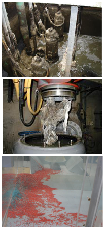
We all aware of the problems that can occur with existing, and in some cases new, assets that necessitate unplanned maintenance.
- Pumping Stations : Pump blockage / Vibration / Grit and Rag accumulation / Poor pump performance.
- Inlet works : Poor screen performance / Flooding / Grit and Rag accumulation / Poor grit removal.
- Flow Distribution Chambers : Poor flow distribution / Instability / Drowning of weirs.
- Process : Poor flow mixing / Poor residence time (contact tanks).
- Storm Tanks : Grit and Rag accumulation.
- CSO Chambers : Premature spill / Poor screening.
Hydrotec consider that a physical or computational fluid dynamic (CFD) model offers a cost effective means of evaluating existing or new assets, identifying problems, developing remedial measures and optimising operating philosophies. Problems that are typically encountered on site can be fully replicated through appropriate modelling techniques Attempts to improve performance on existing assets while live, is considered expensive and time consuming with no guarantee of success. A selection of adverse phenomena are detailed below which typically apply to pumping stations:-
Air
Large amounts of air ingestion will reduce performance and output of the individual pump unit. Air entrained within the pump has the tendency to remain within the inside of the pump impeller, where the centrifugal forces make it accumulate around the impeller hub.
This may lead to increased power requirement and reduced performance and efficiency. The risk of cavitation and pump vibrations also increases with air ingestion. In some extreme cases if there is large amounts of air within the operating volume the pump may cease to function.
Vorticity
Sub-surface vortex formation will occur on any vertical or horizontal surface given close proximity to a pump suction. As flow is drawn into the pump, a rotational mechanism is produced with tightening of a vortex core attached to the flat surfaces.
Sub-surface vorticity of this nature can have a highly detrimental effect on pump performance and efficiency. Vibration issues and increase in mechanical wear are such examples. Not only would the presence of sub-surface vorticity create a velocity imbalance at the pump impeller, any fibrous material caught in the vortex core could bind together and form string like accumulations, which could significantly increase the risk of pump blockage.
Free surface vorticity is exhibited on the water surface and can have enough intensity to pull air from the surface and into the suction pipework, resulting in significant air ingestion.
Solids accumulation
Bottom sediments:
Too low a velocity will result in low shear stresses at the sump floor and build-up of sediments is likely to occur. Cleaning of accumulated solids is a costly and time consuming exercise. In addition, problems arise due to odours and septicity issues with persistent solids deposition and accumulation.
When designing a sump, it is important to avoid any low velocity regions; this can be achieved through the use of appropriately designed benching to promote the regular passage of solids towards the pumps.
Floating debris:
Low velocity regions may also result in excessive build-up of floating debris at the water surface. Floating debris can be avoided with good design and operation. Accumulation of floating debris at the surface of the sump may result in the development of deep rafts of solids, which may clog the pump or system components following ingestion by the pumps.
It is important to use a pump control philosophy to minimise potential solids build up and ensure functions such as alternation between all pump units and automatic cleaning cycles to minimise floating accumulation. Physical modelling can define operating bands and prove the self-cleansing characteristics of stations.
Modelling is a fast and effective method of developing modifications which will offer significant improvements in operational performance. Our aim with this article was to demonstrate how modelling of existing assets can be beneficial in identifying inherent problems of poor performance which necessitate reactive maintenance.
Remember
If you are not sure if the principle requirements to achieve satisfactory operation of the system you are designing can be achieved or you are tasked with ensuring an efficient and low maintenance asset…
then consider your liabilities……………..
And if you are not sure of the potential problems…………….
Or the correct solutions…………
Model It !
Moorfield Estate
Yeadon
Leeds LS19 7YA
e: info@hydrotecltd.co.uk
w: hydrotecltd.co.uk

