


- Overview
- Mixing
- Residence time and Concentration
- Flow paths
Flow mixing and contact tanks
Overview
Computational Fluid Dynamics (CFD) is an ideal modelling platform for the evaluation of mixing and blending applications. The use of CFD is often a more cost effective and expeditious method of analysis, when compared to physical modelling. The components for a CFD analysis for mixing and contact tanks are summarised in the following topic areas.
Mixing
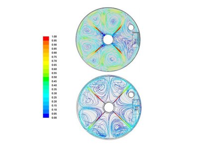
The term "mixing" can refer to either the blending of two or more fluid constituents or to the act of initiating a bulk flow in a single fluid, occupying a tank or basin. Computational Fluid Dynamics (CFD) can readily assess mixing applications and, in some cases, may offer a more cost effective method of analysis when compared to physical modelling. Mixing and blending models can be either steady state or time dependent.
Typical mixing models are steady state, thus providing time averaged results and have a "rigid lid" or "inviscid wall" representing the water surface. These models are appropriate for evaluating particle suspension, indicating if bulk velocity distributions are achieved, evaluating plug flows and mitigating short circuiting in cases where there are balanced inflows/outflows. More complex models may be time dependent with multiple fluid constituents and may have free moving water surfaces. These more complex models may be used for documenting blending efficiency by way of particle or species tracking.
Residence time and Concentration
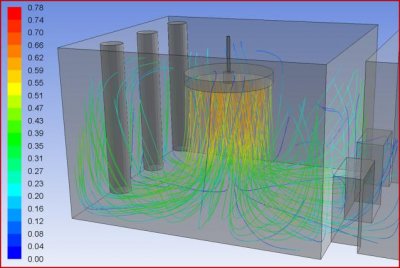
The temporal analysis of a mixed basin or reservoir can be performed with discrete particle or species models. In the discrete particle approach, neutrally buoyant particles are released into the fluid continuum of the CFD model. The pathways these particles take over time are recorded in the CFD model database, thus providing both visual and statistical documentation.
The species model involves the introduction of a tracer fluid with a given concentration. This is analogous to the introduction of a tracer in a physical model, but has some cost advantages since a physical model using tracers, must be undertaken on a total loss system. The dispersion and concentration of the tracer are recorded over time in the CFD model database and, like the discrete particle approach, provide both visual and statistical documentation.
Flow paths
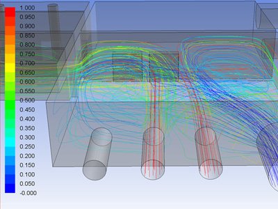
Dye tracing is used in physical models as a visualisation tool to indicate flow paths. In a CFD simulation, this task is accomplished by means of either particle tracking or streak-lines. The lines traced by either method can be coloured by solution variables such as velocity, pressure, turbulence intensity, species concentration or elapsed time. This is a practical means of documenting adverse flow phenomena such as short circuiting, regions of poor mixing, re-circulation zones, jetting, etc.
Moorfield Estate
Yeadon
Leeds LS19 7YA
e: info@hydrotecltd.co.uk
w: hydrotecltd.co.uk

