


Overview
Physical modelling of drop shaft structures can determine the hydraulic characteristics on approach to, and within, the receiving shaft/tunnel and where necessary, provide recommendations to achieve acceptable conditions and improve hydraulic performance. Drop shaft structures can come in many forms; including tangential vortex drops, cascades, scroll type intakes, etc.
Drop structure design criteria may be defined as follows:-
- Verify the geometry of the conceptual drop structure design (i.e., confirm drop pipe diameter, receiving shaft diameter etc.).
- Maximise energy dissipation within the drop structures and the receiving shaft, whilst minimising the potential for scour.
- Provide a stable transition of flow from high to low level under free discharge and surcharged operation.
- Maintain hydraulic stability within the receiving structure to prevent rapidly varied flow transitions, such as a hydraulic jump.
- Provision of a smooth, uniform and steady transition to the receiving structure and downstream system.
- Maximise the air release within the receiving structure under all conditions of operation.
- Stabiliseand control air transport and release within the shaft and outlet structure.
- Minimise turbulence, noise and vibration within the structure.
Energy Dissipation
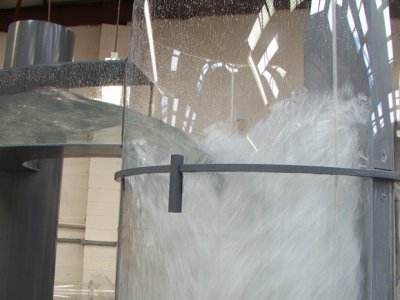
The purpose of any drop structure is to transfer flow from high to low level as simply as possible and in a controlled environment, whilst maximising energy dissipation. Dissipation of residual energy may be required to ensure stable operation of the structure. Physical modelling can readily evaluate alternative arrangements to maximise the dissipation of energy.
Air Transport
The transport of entrained air to the downstream system can result in the development of unsteady flow characteristics, such as surge pressures, flow oscillations and restriction.
Physical modelling can determine air entrainment, transport and release characteristics throughout the structure, allowing alternative configurations to be compared and optimised.
Hydrotec have developed air capture/analysis techniques that allow a quantitative assessment of alternative structures. Such methods allow a direct comparison of alternative designs over a comprehensive test matrix.
Pressure measurements
To aid in the structural and hydraulic design of a drop structure, dynamic pressure variations can be measured throughout the structure at pertinent locations. Measurements are taken using pressure transducers and data loggers to provide a real time assessment of dynamic performance.
Scroll and vortex calibration
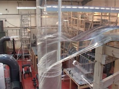
To achieve acceptable operation, the performance of the inlet structure is critical to ensure an effective transition from an inlet conduit to a vertical drop pipe. The inlet structure transforms the approach flow from a straight, normally rectangular and nearly horizontal channel into a helicoidal vertical flow path. The shape of the inlet structure can be circular, spiral, screw or tangential. The use of a physical hydraulic model is ideally suited to verify the inlet structure design and provide detailed calibration.
Solids assessment

A comprehensive range of simulated solids can be introduced to a physical hydraulic model to assess the behaviour of solids within the system. This is critical to determine the potential for solids deposition/accumulation within the system. Where areas of persistent long term deposition are identified, there is a potential for a loss in hydraulic performance and associated operational and maintenance concerns, such as odour, septicity and the requirement for safe removal.
Hydraulic profile
A physical hydraulic model allows a comprehensive assessment of the hydraulic grade line produced through each of the individual elements of the drop structure. Water level measurements are undertaken with piezometric tapings and comprise the upper limit of the intermittent and top water surface. These measurements comprise the static head, i.e., excluding the velocity head; this can be useful when assessing the maximum permissible water levels.
Moorfield Estate
Yeadon
Leeds LS19 7YA
e: info@hydrotecltd.co.uk
w: hydrotecltd.co.uk

