


Overview
Regardless of size or pumping capacity it is vital that an acceptable operating environment is achieved within all pumping stations. Physical hydraulic modelling can readily assess pump performance, general hydraulics and solids handling.
Physical modelling can accurately reproduce all pertinant full scale hydraulic effects such as velocity distributions, air entrainment, vorticity etc.
A physical model can quickly assess pump intake conditions for all potential pump combinations and operating levels.
A physical model offers a fast method of developing solutions.
A physical model can give a reliable indication as to the behaviour of various solids types in a system.
A physical model can readily define minimum operating levels.
In applications where development options need to be studied for various screen, pump and sump combinations a Physical Model is the best method of analysis to use.
Typical adverse conditions can be readily observed, these may be summarised by the following:-
- Vorticity, sub-surface and surface
- Air entrainment
- Solids accumulation
- Pre-swirl rotation
Vorticity
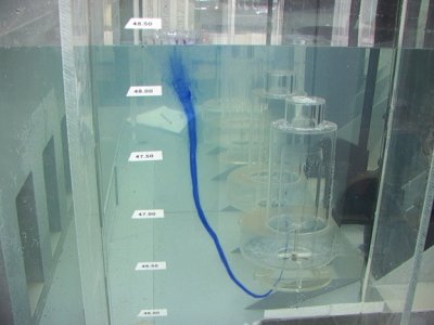
Vorticity of any nature can have detrimental effect a pump intake conditions. Vortices are a common feature of unacceptable pump operation, resulting in cavitation, uneven blade loading, noise and vibration. There are several different types of vortices. The most commonly recognised type is the free surface vortex, which can have varying degrees of intensity from weak surface vortices to fully developed vortices with a continuous air core that extends from the free surface into the pump intake. Surface vorticity with sufficient energy to induce an air core will result in significant air ingestion to duty pumps.
Less well known, but just as common is submerged vorticity, which forms beneath the water surface, against a wall, or between two pumps. This type of vorticity can achieve high rotational speeds associated local reduction in pressure and subsequent high cavitation potential.
Sub-surface vortices are potentially more destructive than surface vorticity but often fail to be identified as the cause of excessive pump vibration and cavitation erosion of impeller vanes. In foul water applications submerged vorticity can lead to the twisting together of fibrous waste material to form string like accumulations which can significantly increase the risk of pump blockage.
Air entrainment
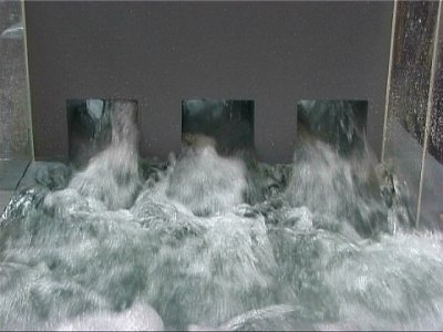
It is widely known that even minor air entrainment, of some 3 to 4% of the volume, will lead to a clear reduction in pump performance and loss in efficiency, the severity depends upon the quantity of air entrained and the pump type. The expansion of ingested bubbles within the impeller may result in mechanical imbalance, vibration and acceleration of mechanical wear. Normal design practices recommend the exclusion of any air entrainment in the approach flow to the pump intakes.
Large amounts of air ingestion will reduce performance and output of the individual pump unit. Air entrained within the pump has the tendency to remain within the inside of the pump impeller, where the centrifugal forces make it accumulate around the impeller hub. This may lead to increased power requirement and lowered performance and efficiency. The risk of cavitation and pump vibrations also increases with air ingestion. In some extreme cases if there is large amounts of air within the operating volume, the pump may cease to function.
Solids accumulation
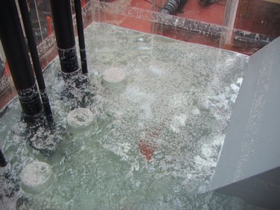
It is important to design a station to minimise build-up of solids within the sump and prevent accumulation of floating debris at the water surface.
Bottom sediments:
Too low velocity will result in low shear stresses at the sump floor and build-up of sediments is likely to occur. Cleaning of accumulated solids is a costly and time consuming exercise. In addition, problems arise due to odours and septicity issues with persistent solids deposition and accumulation.
When designing a sump, it is important to avoid any low velocity regions; this can be achieved through the use of appropriately designed benching to promote the regular passage of solids towards the pumps.
Floating debris:
Low velocity regions may also result in excessive build up of floating debris at the water surface. Floating debris can be avoided with good design and operation. Accumulation of floating debris at the surface of the sump may result in the development of deep rafts of solids, which may clog the pump or system components following ingestion by the pumps. It is important to use a pump control philosophy to minimise potential solids build up and ensure functions such as alternation between all pump units and automatic cleaning cycles to minimise floating accumulation. Physical modelling can define operating bands and prove the self-cleansing characteristics of stations.
Pre-swirl rotation and velocity distribution
Pre-swirl rotation
Pre-swirl changes the flow conditions at the pump inlet, which results in a change in the relative impeller speed. This, in turn, causes a change in pump performance, which can lead to over loading the motor or reduced pump performance. Excessive pre-swirl can also result in bearing wear and cavitation across the impeller area. Pre-swirl usually originates from asymmetric velocity distribution in the approach channel, which evolves into a pre-swirl at the pump inlet. The Hydraulic Institute recommends a pre-swirl angle that does not exceed 5 degrees, calculated from the ratio between the tangential velocity and the axial velocity.
Velocity distribution
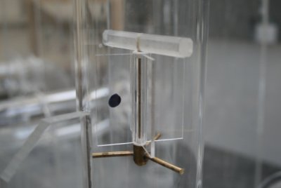
The variation in velocity distribution across the plane of the propeller inlet can affect the pump in two principal ways. Firstly, any significant variation in approach velocity as individual blades rotate one full revolution can result in cyclic blade loadings, sufficient to cause fatigue failure of the individual blade root or fixing. Secondly, the net combined effect of the velocity distribution on all four blades can result in cyclic variations in the axial loads on the rotating assembly including bearings and mechanical seals.
The cross-sectional velocity distribution is determined within a modelled pump unit across a plane within the pump intake at an elevation equal to the leading edge of the pump impeller vanes. The velocity distribution is measured using a pitot static tube array. The array comprises four pitot tubes, offset from the horizontal and vertical axes at a set incremental distance from the impeller hub. Eight rotations of the array through 45 degrees produce 32 measurements of point velocity over the full cross section.
Moorfield Estate
Yeadon
Leeds LS19 7YA
e: info@hydrotecltd.co.uk
w: hydrotecltd.co.uk

