


BELFAST SEWERS-VORTEX DROP STRUCTURES
Client: MORGAN FARRANS JV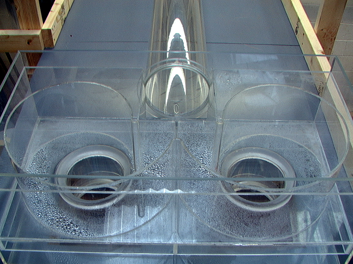
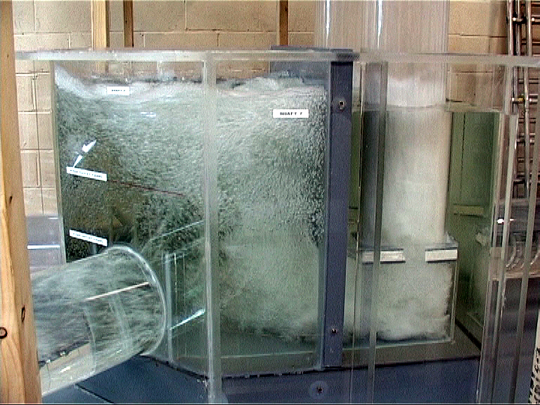
Scale: 1:8
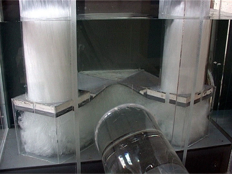
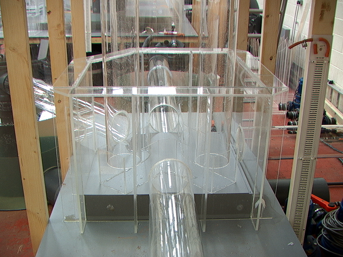
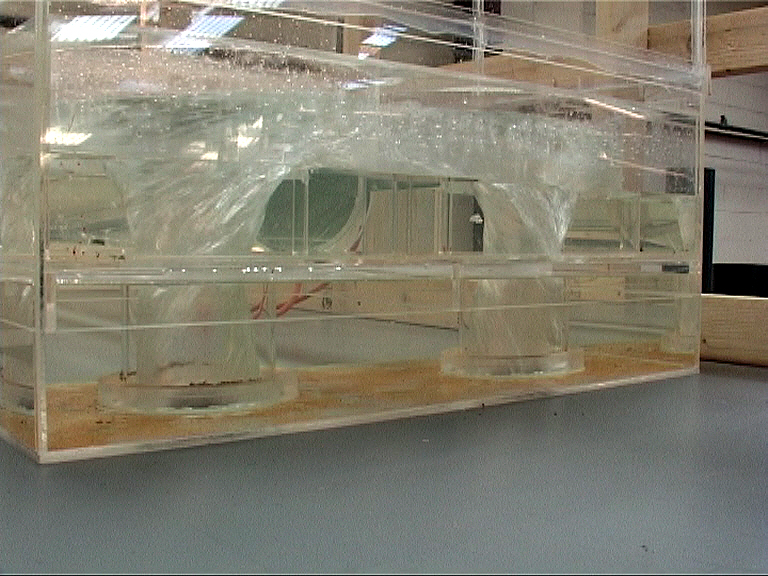
The model study was required to investigate concerns regarding the hydraulic performance of the receiving shaft/tunnel arrangements and to establish modifications, where considered necessary, to achieve satisfactory performance within the receiving shaft/tunnel. The model test was not proposed to provide a detailed design verification for each element within the six individual vortex drop structures.
A generic model arrangement was constructed to investigate the hydraulic characteristics of the receiving shaft/tunnel arrangements for each of the six drop shafts. The receiving shaft was modified for each of the six arrangements to provide a representation of the outlet conditions at each shaft.
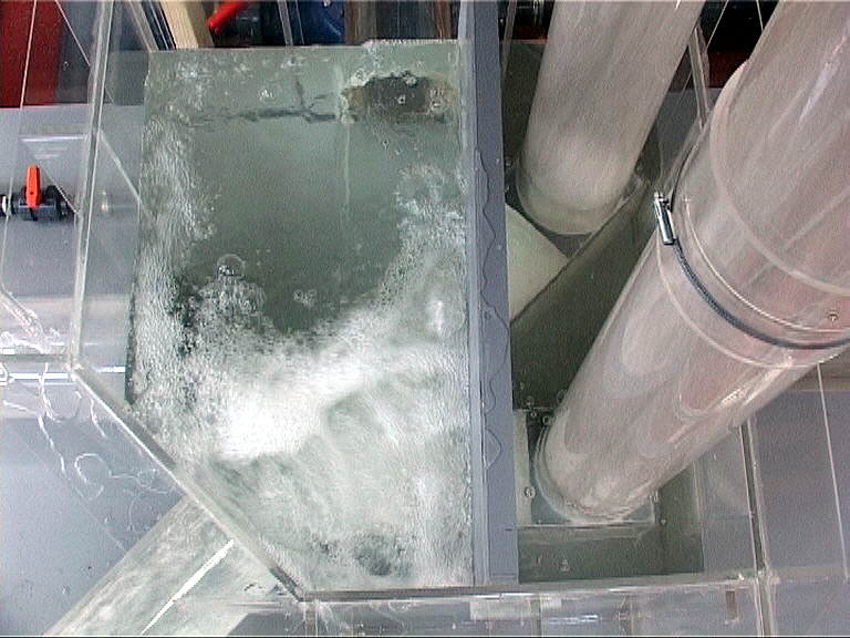
Each vortex drop shaft arrangement was tested at up to the design 1 in 30 year storm flow and conditions of free discharge and surcharged operation were simulated within the receiving shaft.
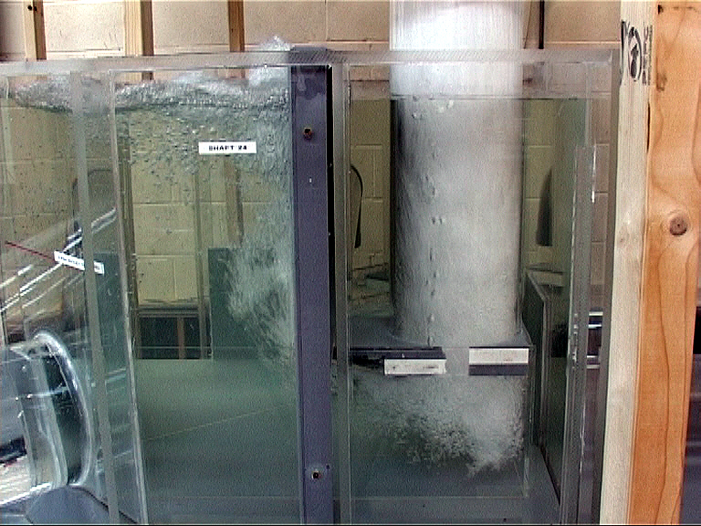
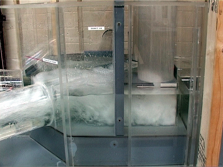
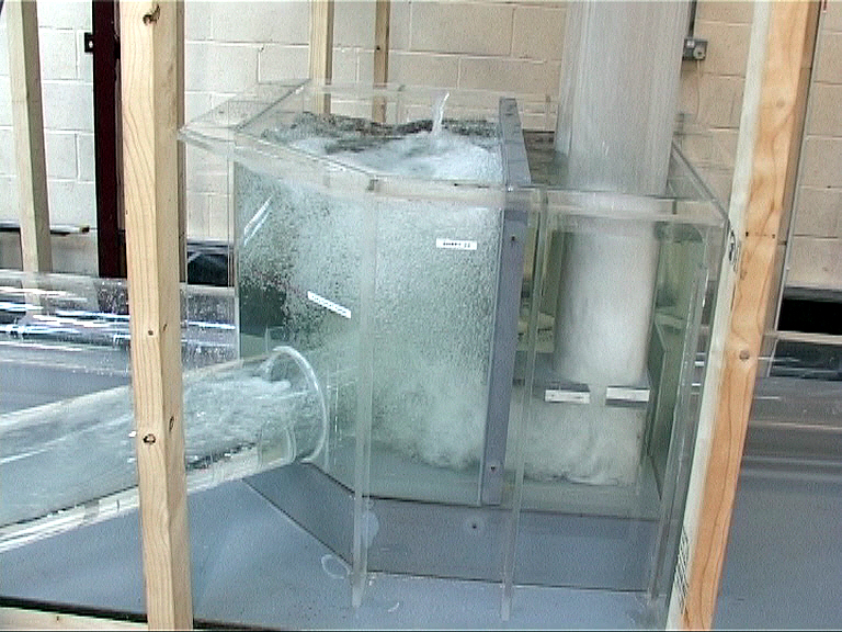
Shaft 24
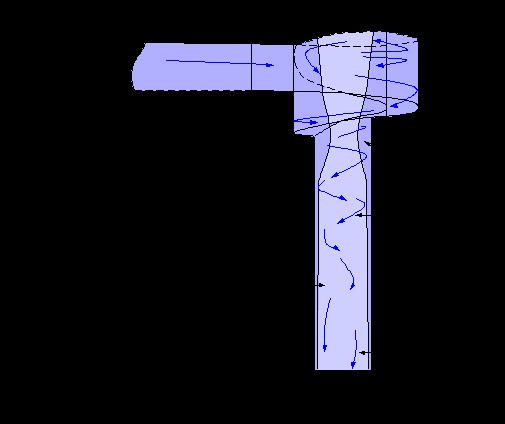
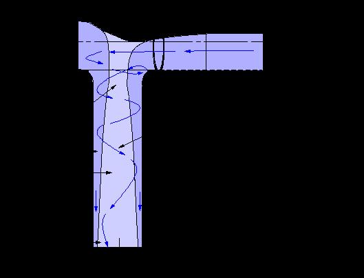
The proposed arrangement of the vortex drop pipes within Shaft 24 was considered to provide an effective, safe and stable hydraulic transition from the high level sewer to the low tunnels. The arrangement was considered to provide very effective energy dissipation with minimal noise and to maintain stable conditions within the receiving shaft and the downstream tunnel.
Shaft 7
The proposed arrangement of the vortex drop pipes within Shaft 7 was considered to provide an effective, safe and stable hydraulic transition from the high level sewer to the low tunnels. The arrangement was considered to provide very effective energy dissipation with minimal noise and to maintain stable conditions within the receiving shaft and the downstream tunnel.
Shaft 26
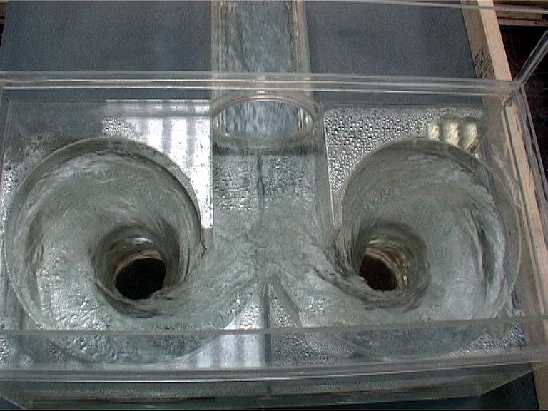
Testing determined that, although relatively turbulent operation was evident at the design flow condition, stable and acceptable flow conditions were produced within the proposed outlet arrangement of Shaft 26, under operation over the full design flow and level range.
Shaft 25
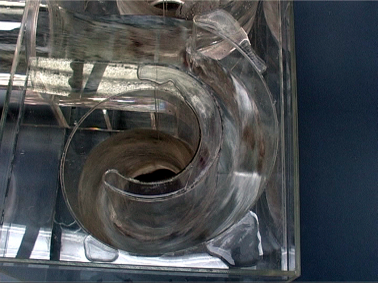
The initial proposed arrangement of Shaft 25 resulted in high velocity jet penetration to the outlet tunnel, which was considered to pose a high risk to the integrity of the structure. A modified arrangement was proposed that comprised a re-orientation of the drop pipe outlet culvert. Testing determined that, although relatively turbulent conditions were evident under free discharge operation at the design flow condition, stable and acceptable flow conditions were produced within the proposed revised outlet arrangement of Shaft 25.
The modified arrangement ensured that energy dissipation was maximised within the drop pipe outlet culvert and the receiving shaft, this should ensure that a stable hydraulic transition is produced from the high level sewer to the low level tunnels over the full design flow and level range.
Shaft 10
Testing determined that, although relatively turbulent conditions were evident under free discharge operation at the design flow condition, stable and acceptable flow conditions were produced within the proposed arrangement of Shaft 10.
Shaft 4
Testing determined that, although relatively turbulent operation was evident at the design flow condition, stable and acceptable flow conditions were produced within the proposed outlet arrangement of Shaft 4, under operation over the full design flow and level range.
Recommendations were made for minor alterations at the outlet from the drop pipes to improve energy dissipation and air release characteristics for all shafts.
Moorfield Estate
Yeadon
Leeds LS19 7YA
e: info@hydrotecltd.co.uk
w: hydrotecltd.co.uk

