


Bretton Park Lower Lake Reservoir
Client: JBA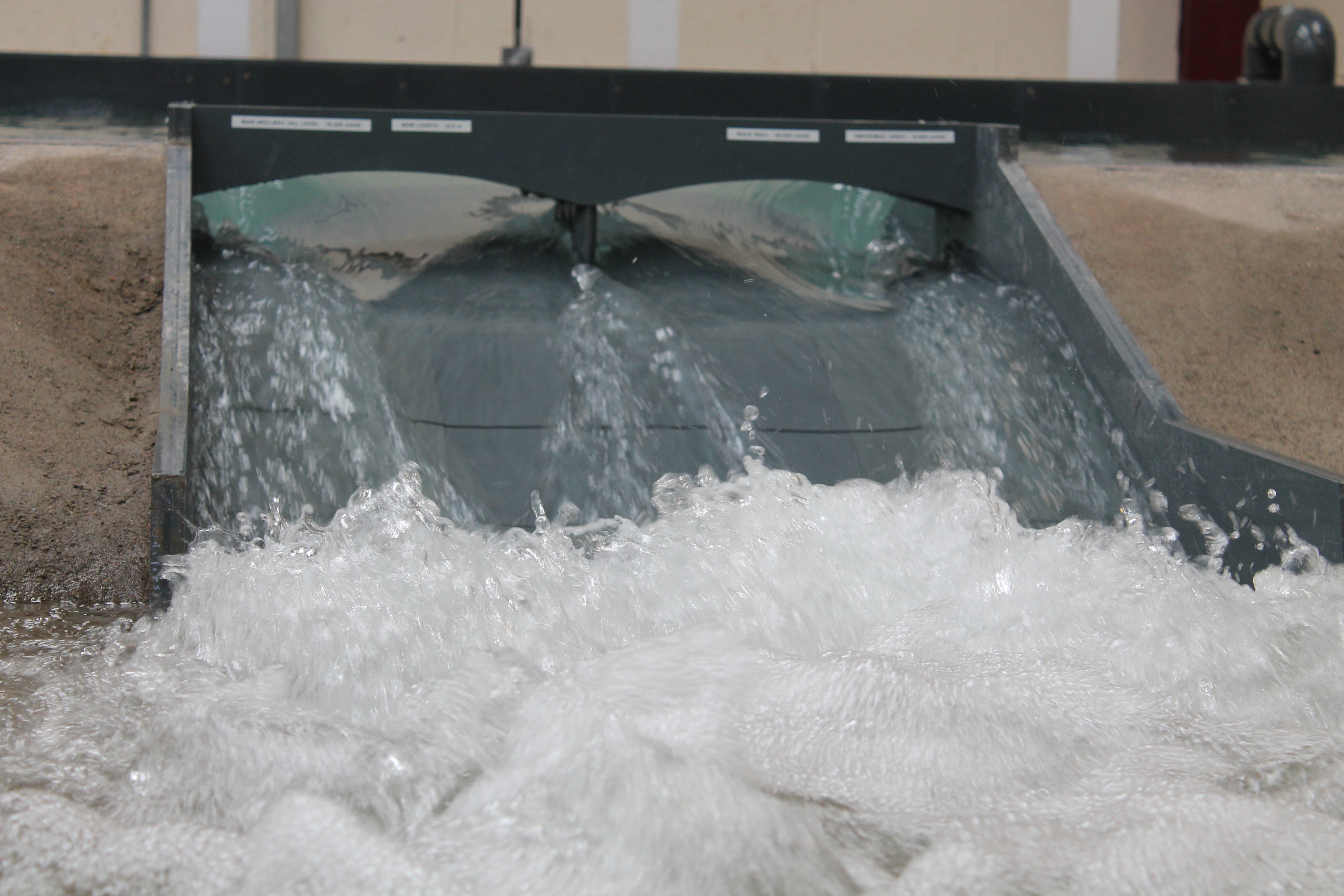
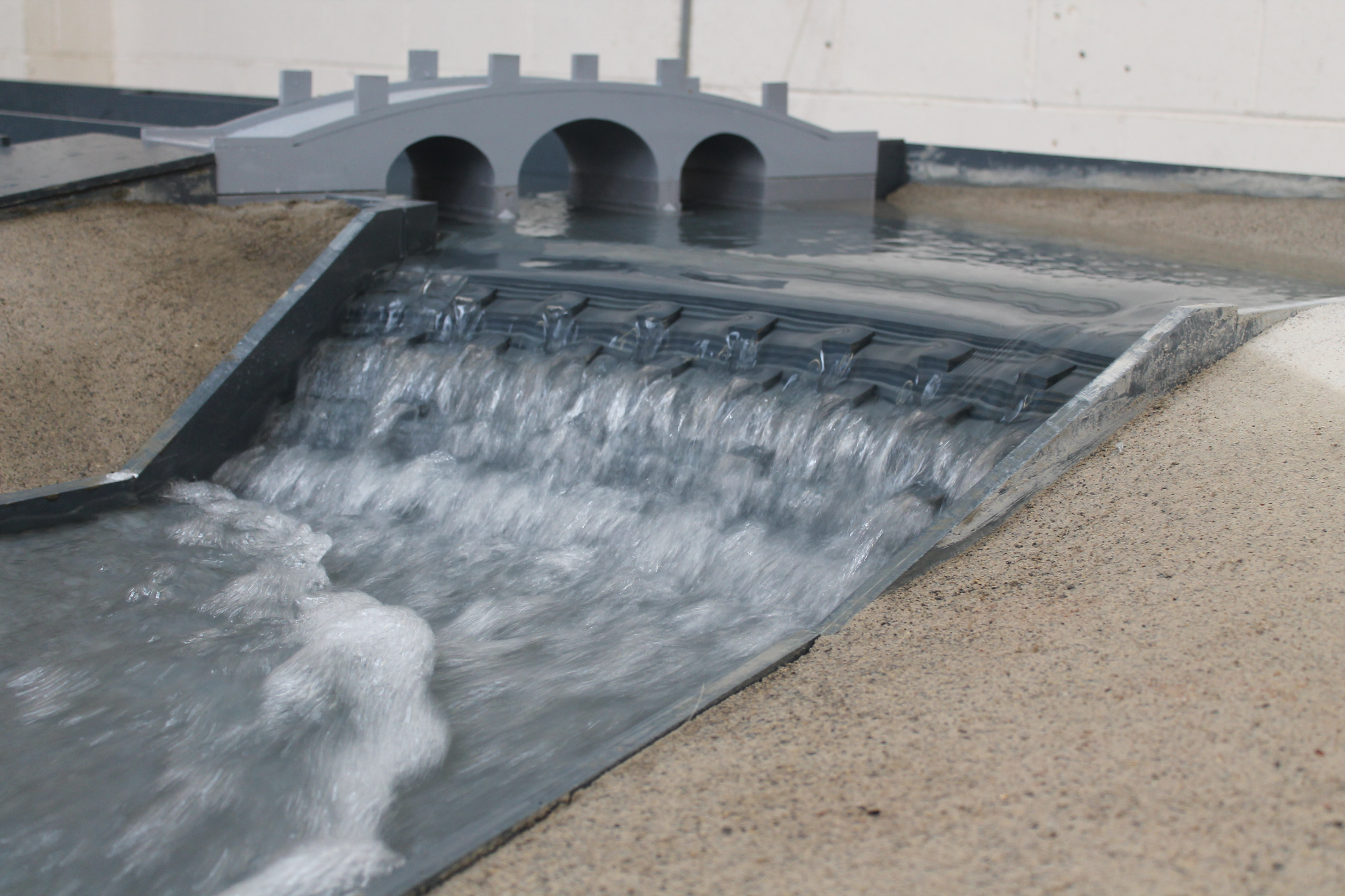
Scale: 1/25th
Bretton Park Lower Reservoir is located at West Bretton, Wakefield, within the grounds of the Yorkshire Sculpture Park. The reservoir is impounding, formed by an earth fill dam embankment some 12.0 m high and of approximately 150 metres in length. The reservoir capacity to top water level is stated as 288,636 m3 in the Form of Record. The reservoir is located directly downstream of Bretton Upper Reservoir, which is located approximately 2.50 m higher than the lower lake. Both the Upper and Lower Reservoirs were built as amenity reservoirs for Bretton Hall and now form major landscape features within the Yorkshire Sculpture Park, which leases the area from Wakefield Council.
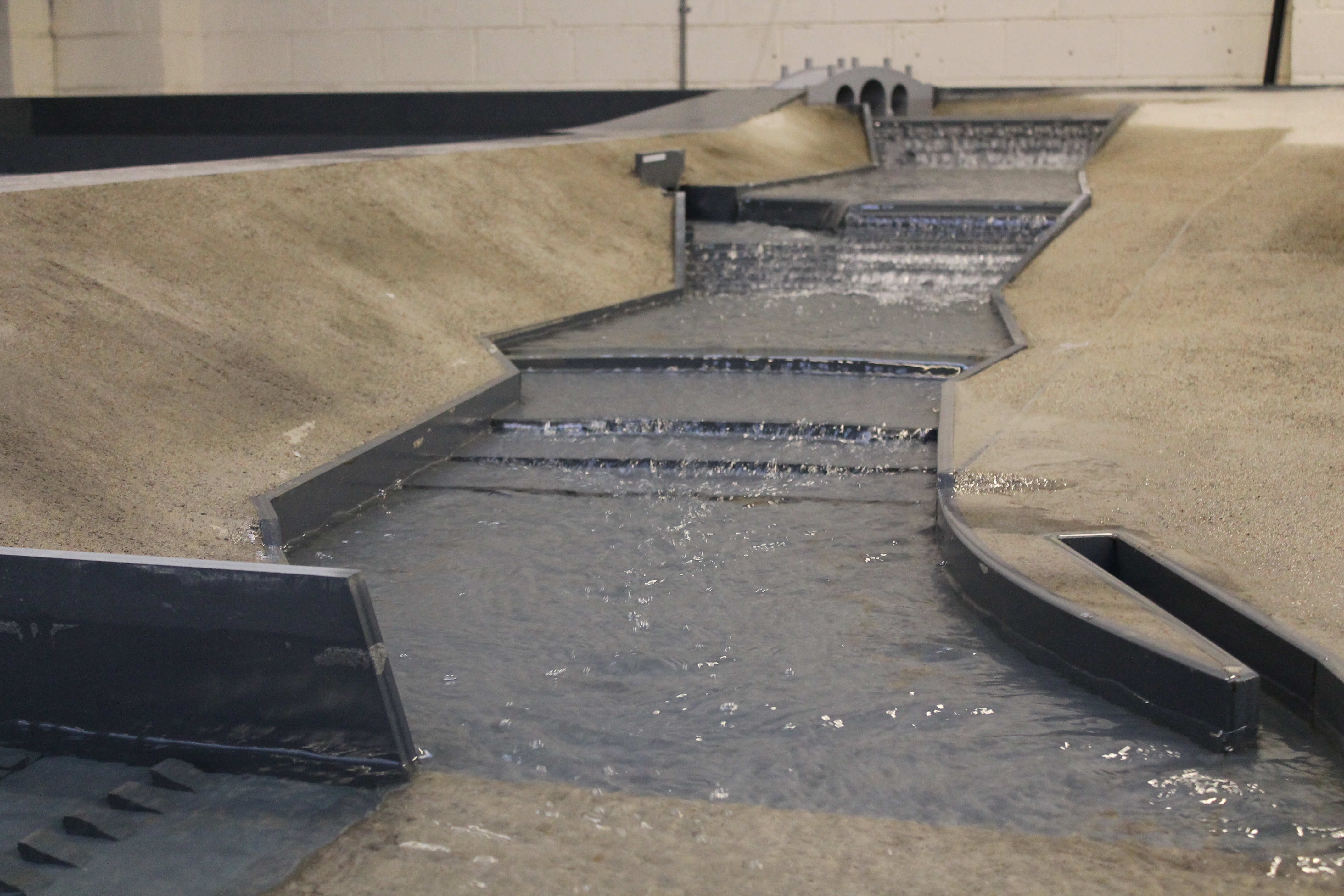
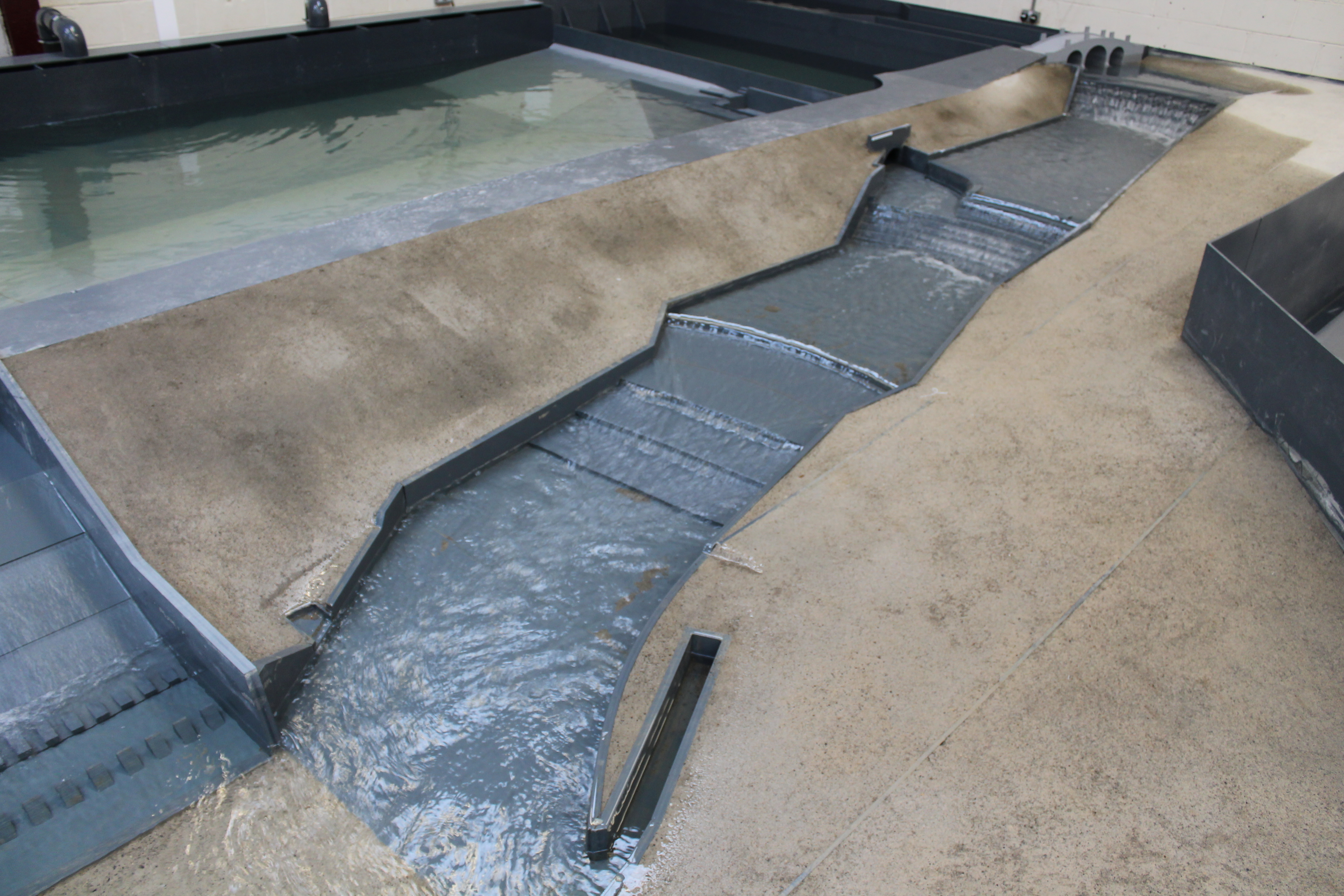
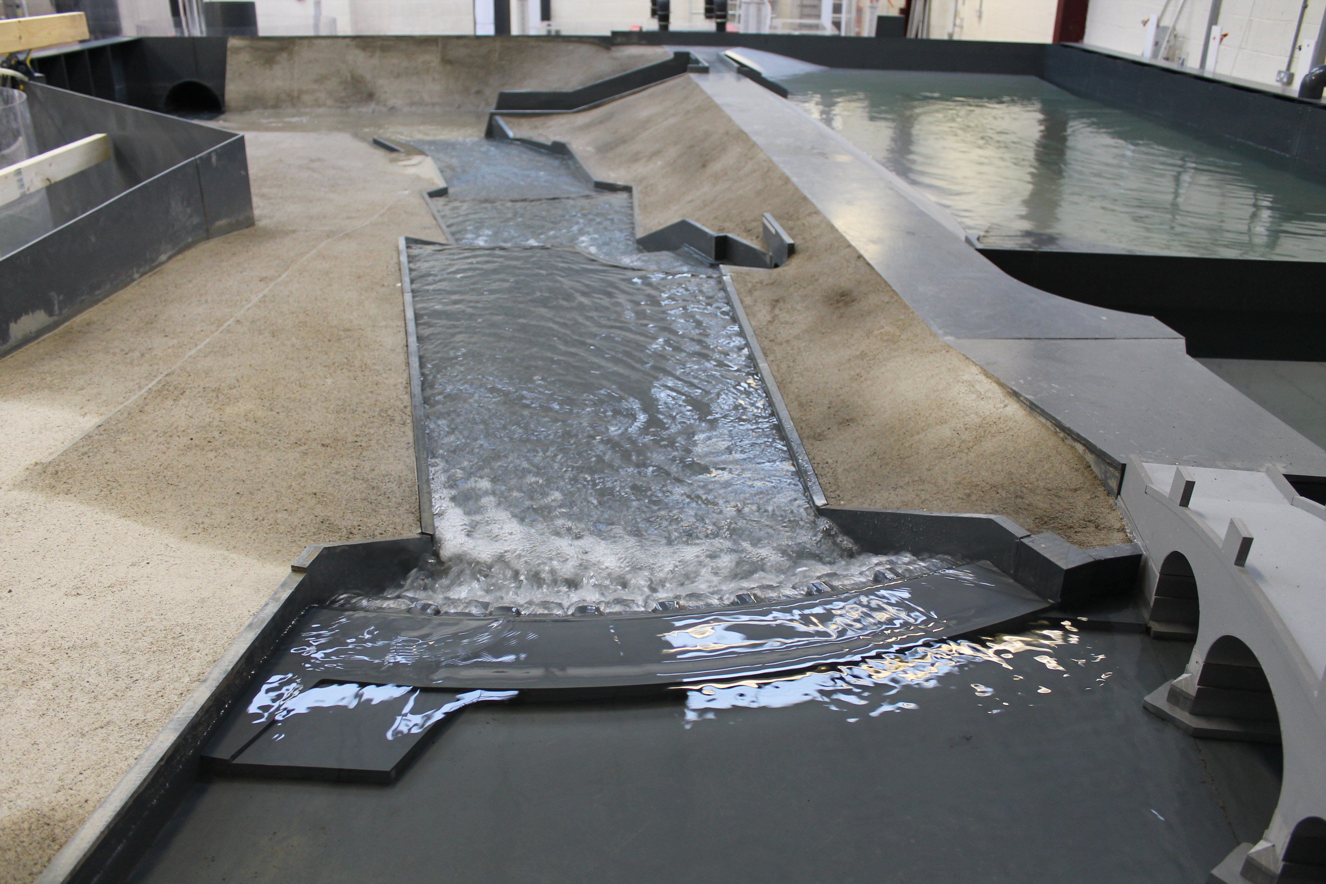
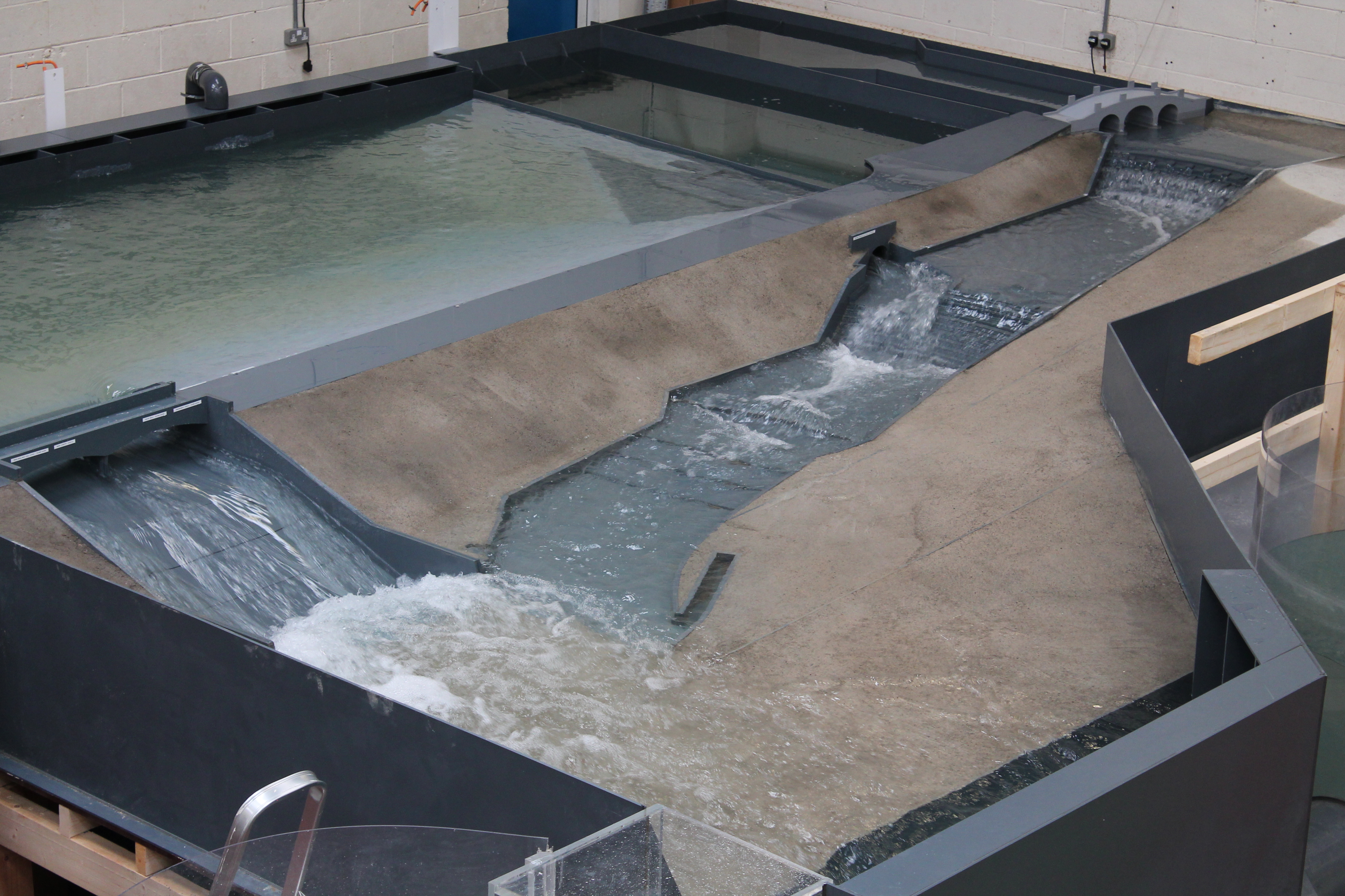
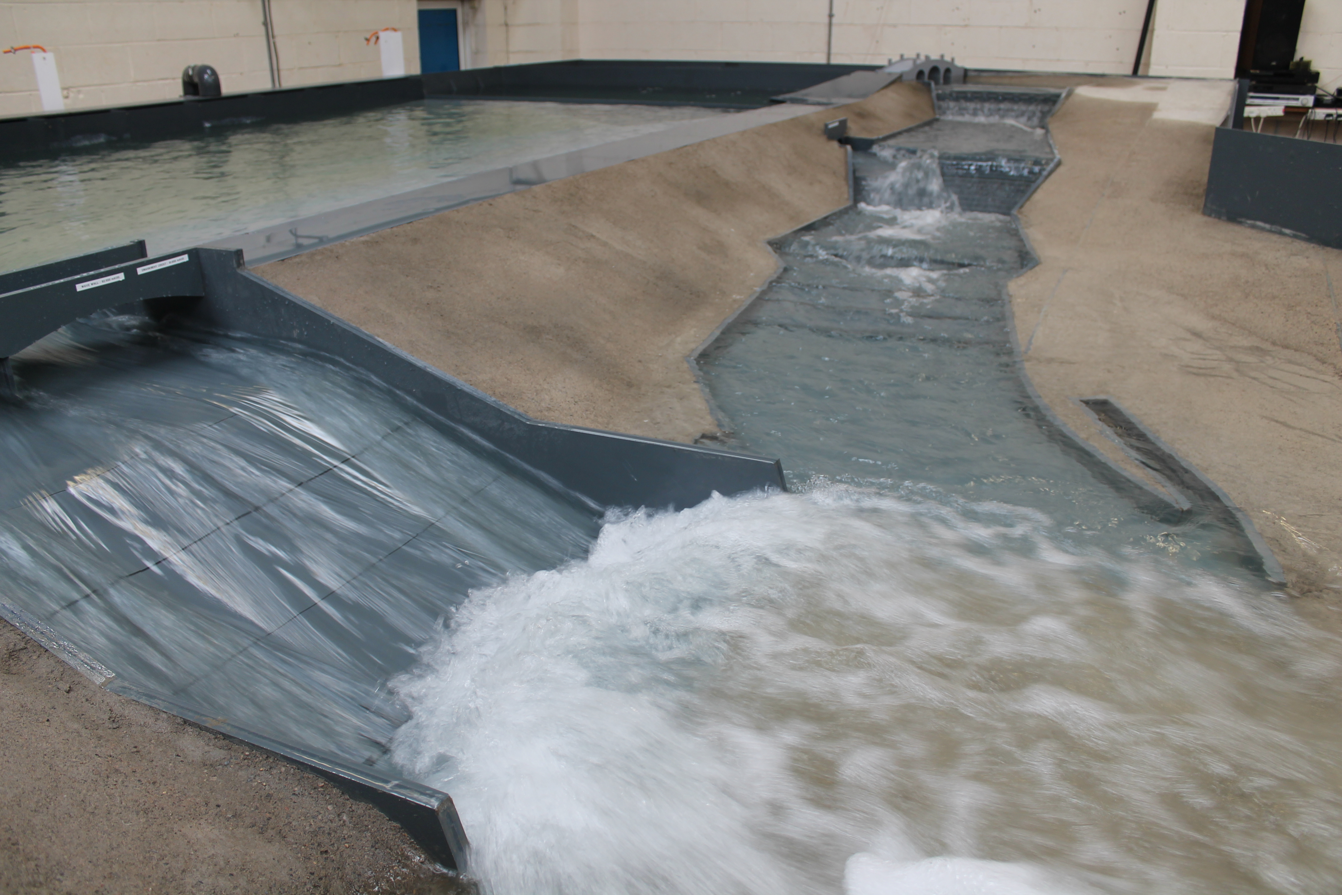
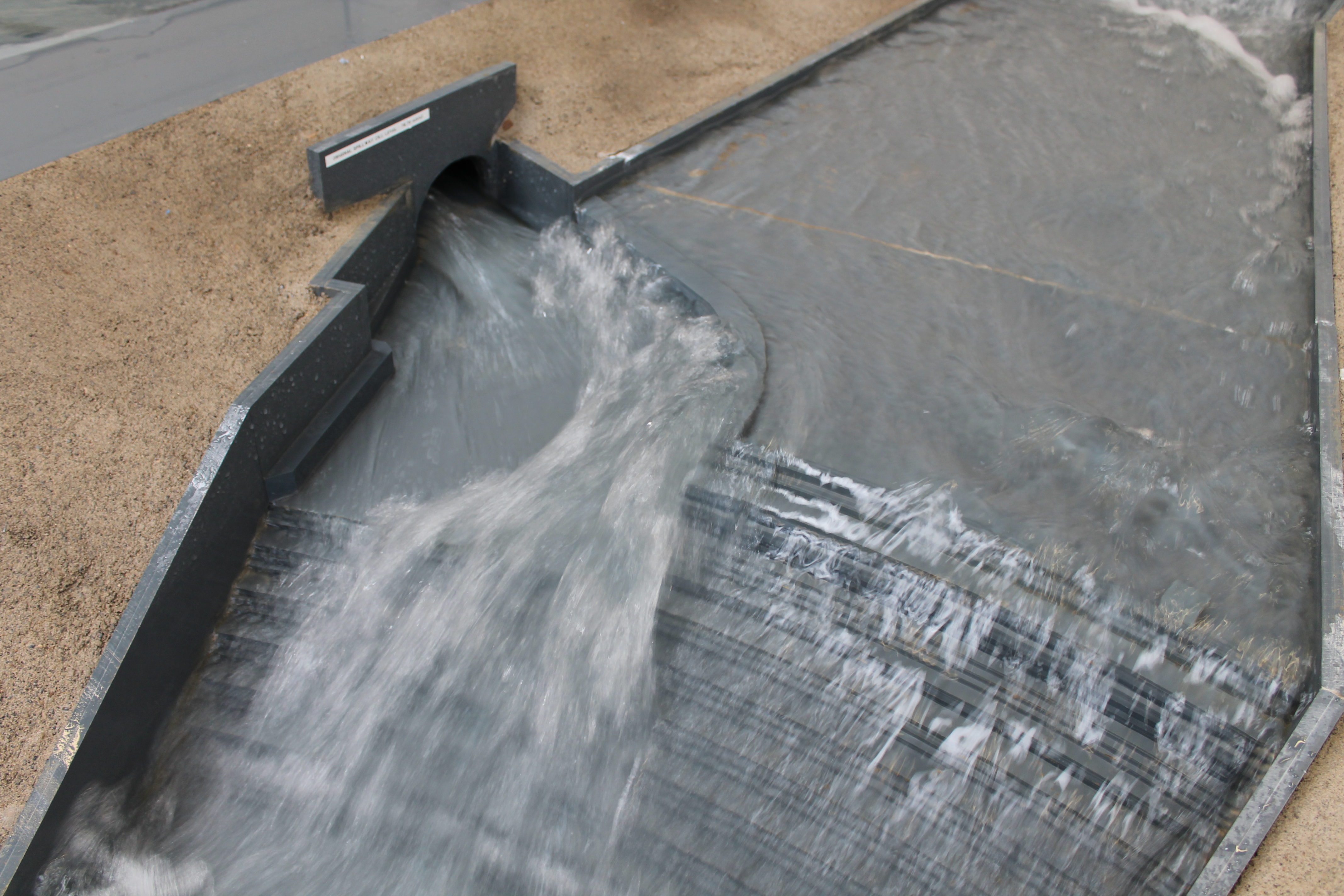
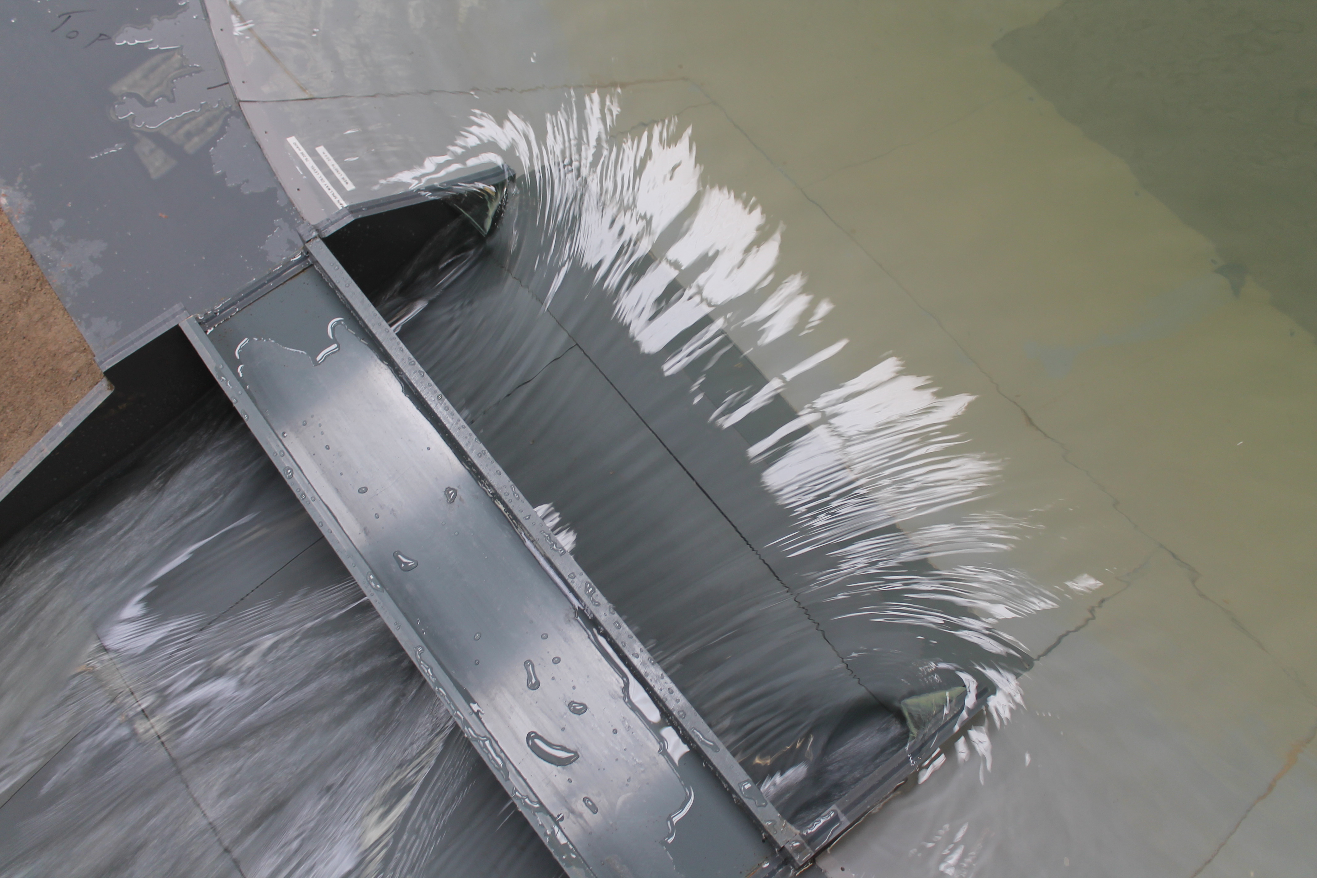
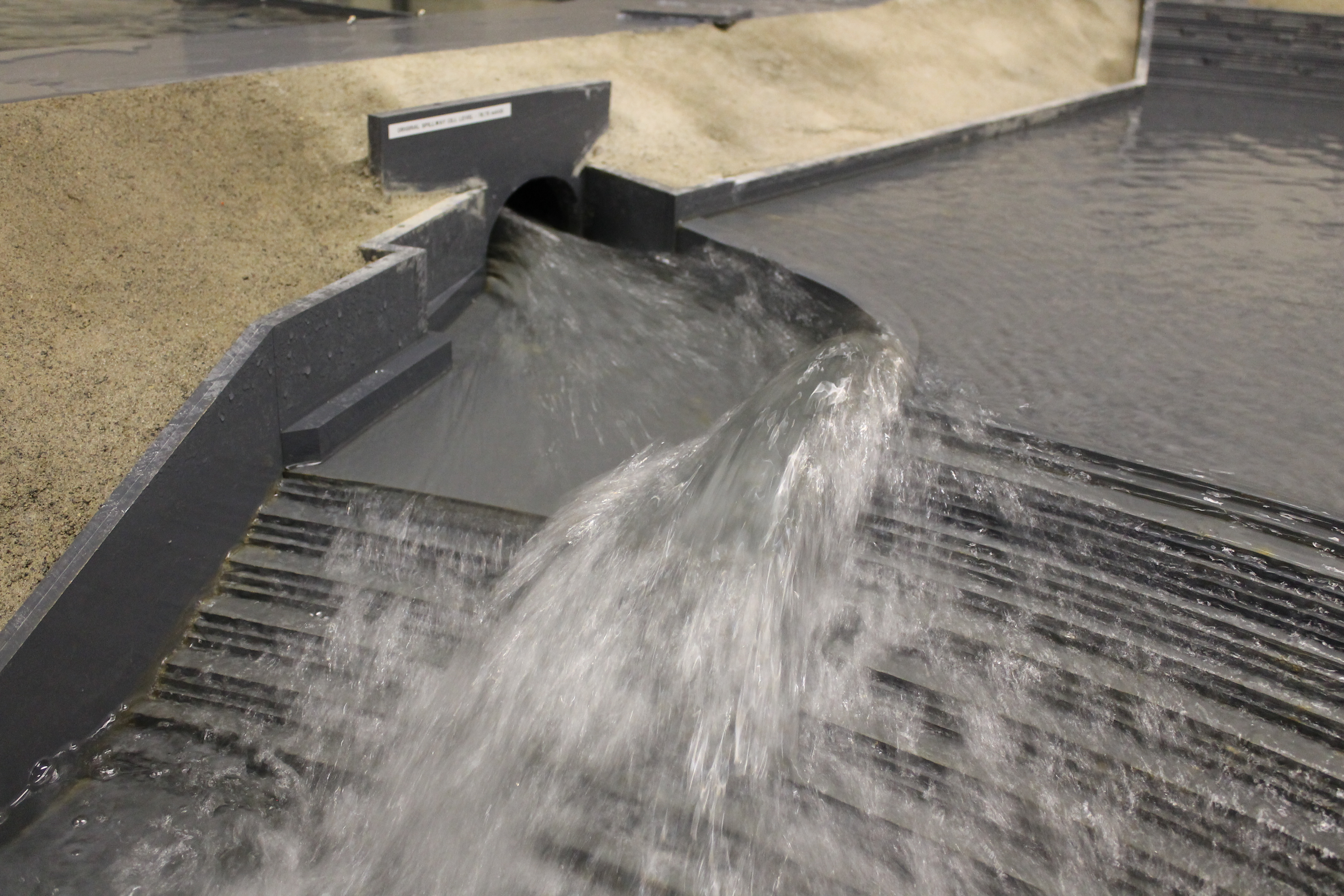
Historically, flood flows were predominantly handled by the River Dearne and the Original Spillway. Concern was raised in regard to the course of the River Dearne, which carries flow from the cut and the original spillway within a walled channel located immediately at the toe of the downstream embankment. The erosion of the channel bed and side walls provided a risk of subsequent erosion to the embankment under a flood flow condition.
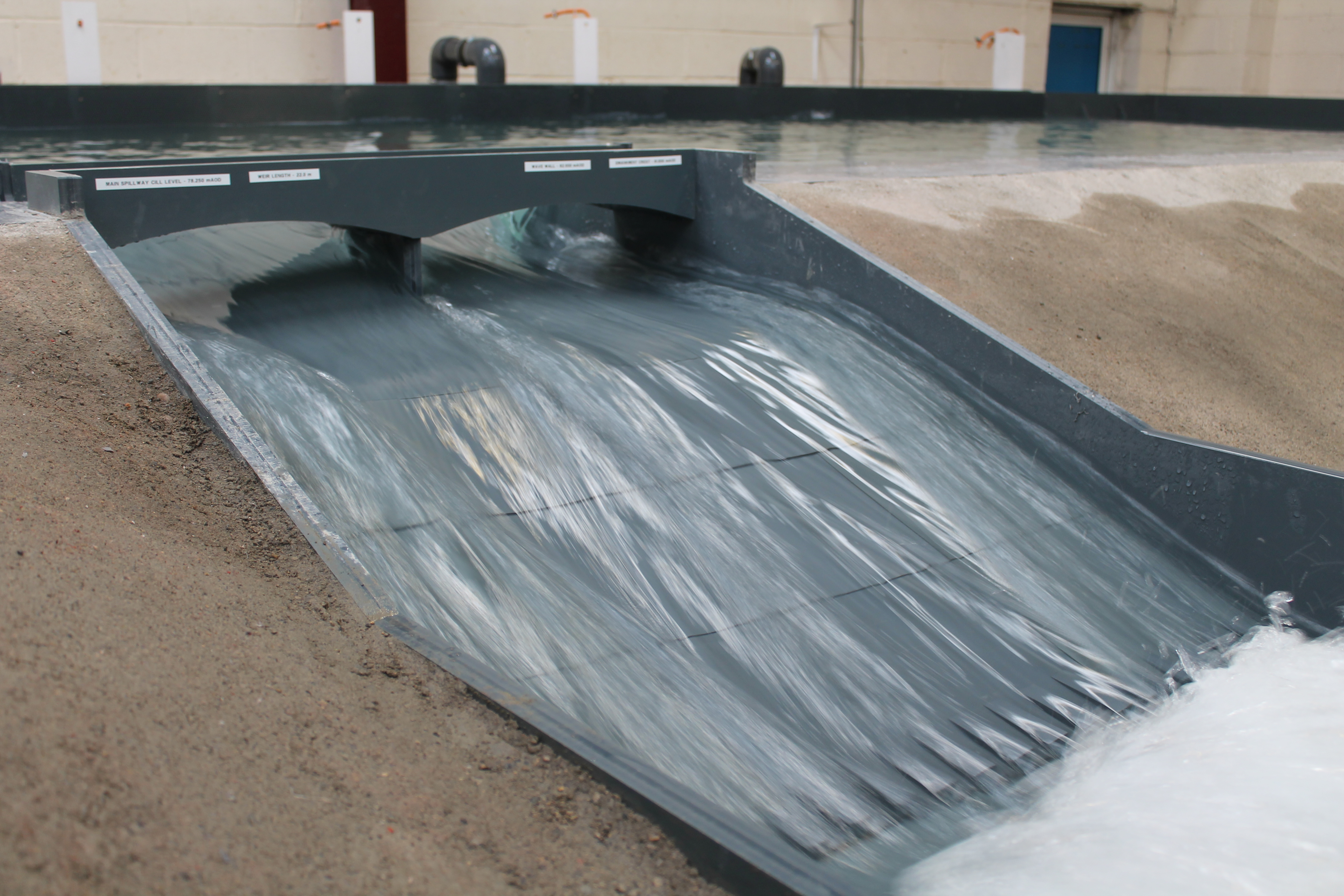
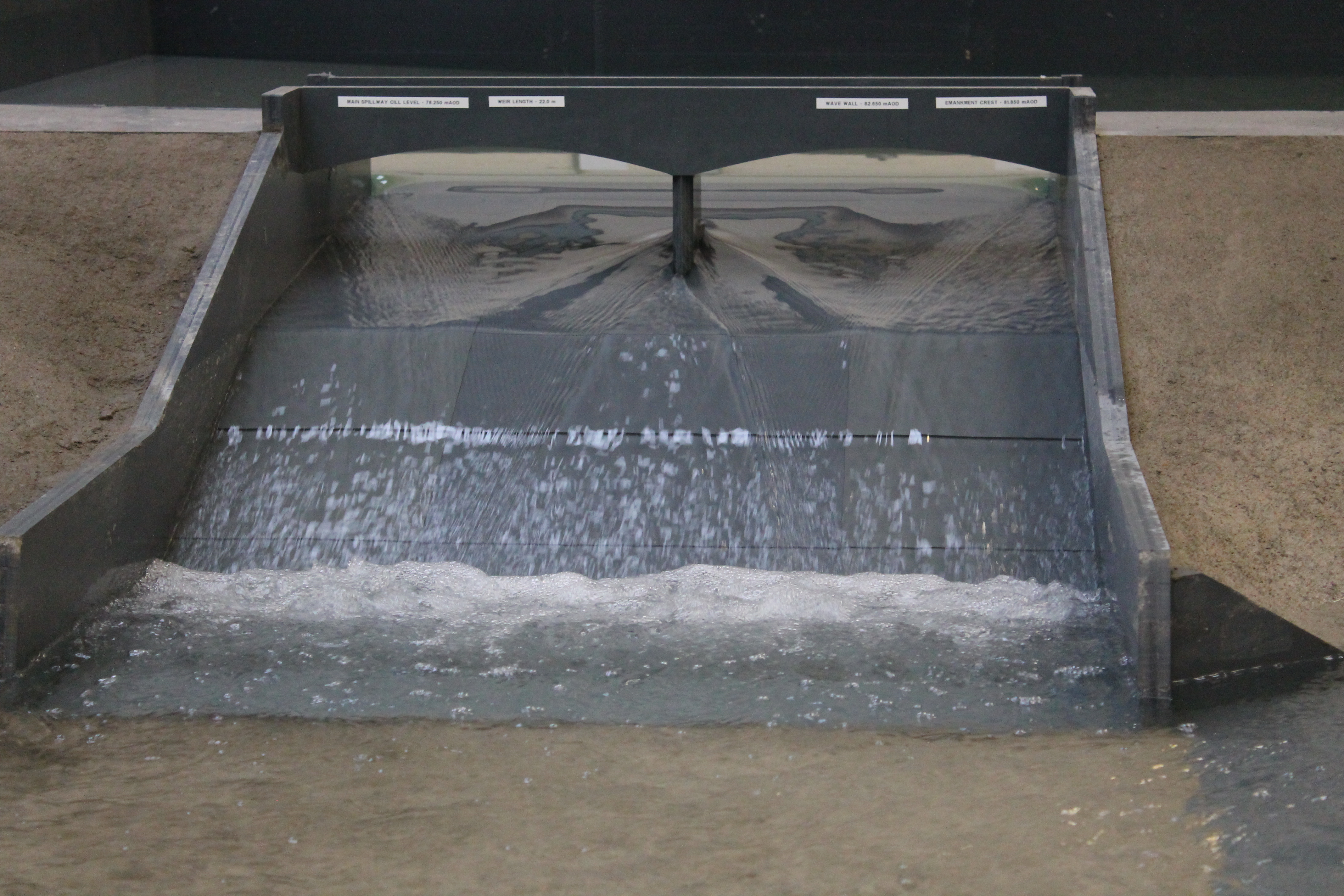
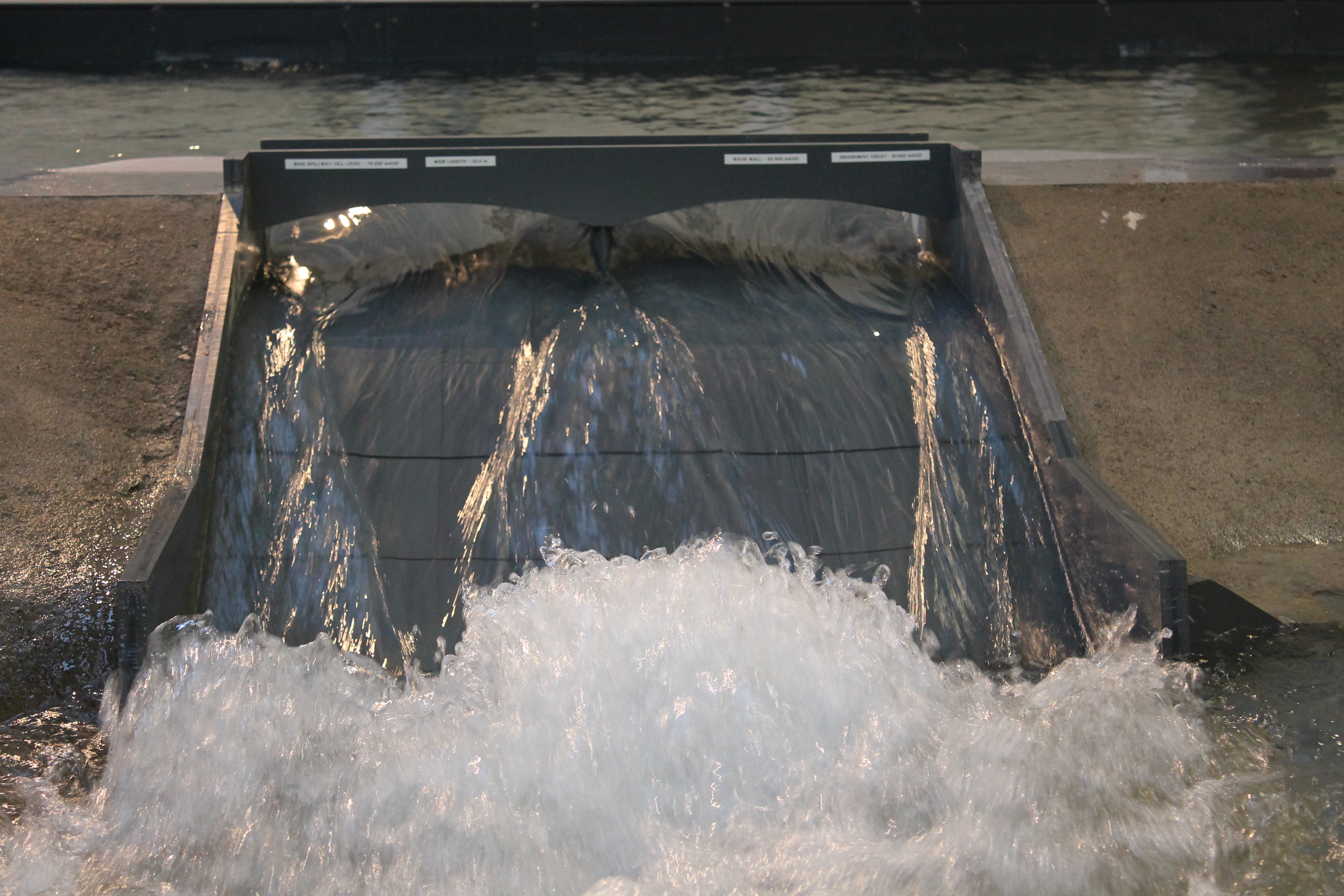
The construction of the ‘Main Spillway’ in 1992 and the raising of the inlet to the original lower lake culvert, by means of a control weir, have resulted in virtually no flood flow being discharged through the original culvert, with flow tending to pass over the lower Main Spillway instead.
The recent grant aided restoration works at the upper lake have had the beneficial effect of a major reduction in the excess flows that will pass down the cut and discharge over the upper cascade and down alongside the toe of the lower dam embankment, with excess flows instead discharged first into the Lower Reservoir and then over the Main Spillway. This by-passing of the cascade is effective under low to medium flood scenarios; however, under high flood flows, the original spillway will continue to discharge potentially high flow through the 3.50 m wide culvert and along the toe of the embankment, resulting in a continued risk of erosion to the embankment.
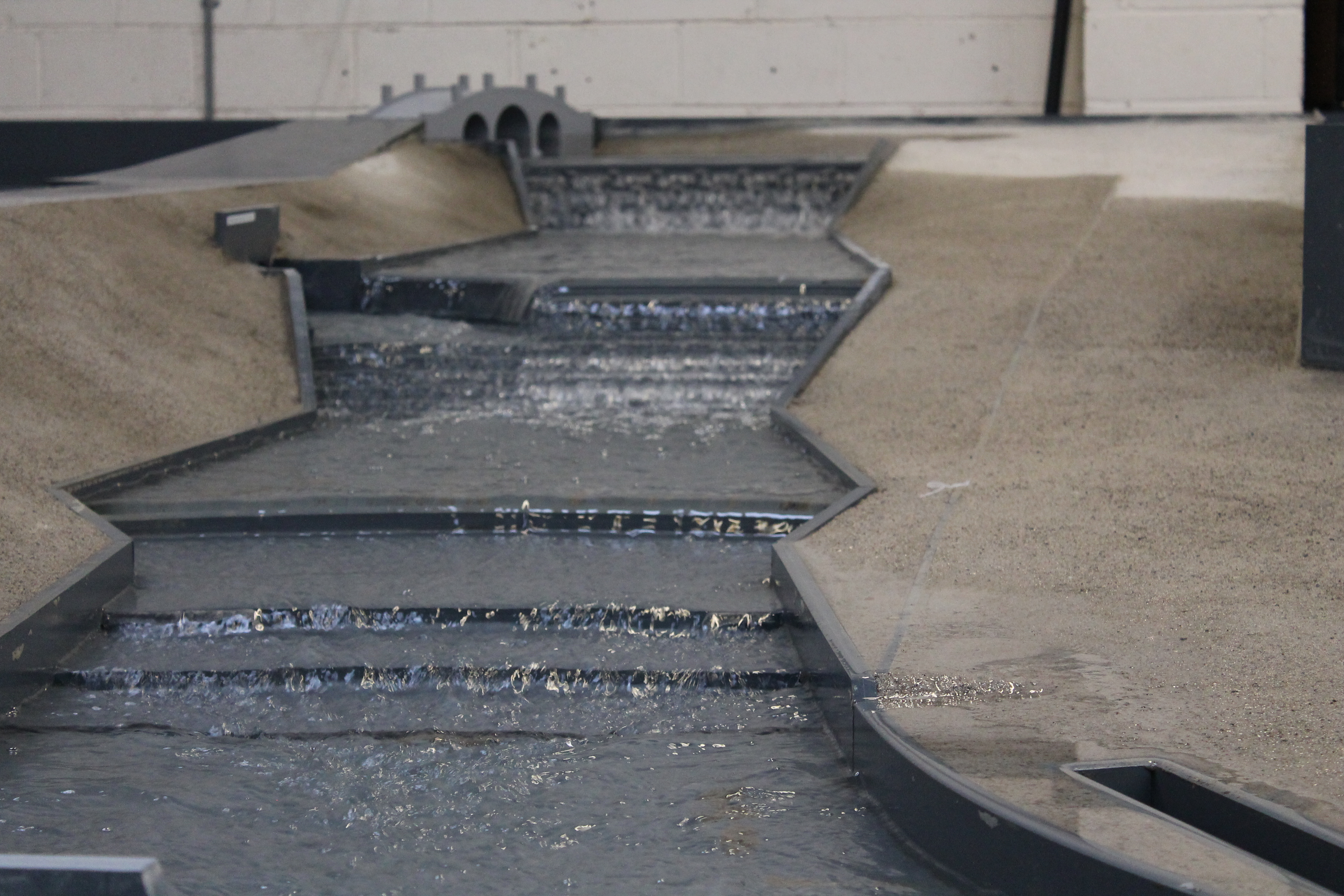
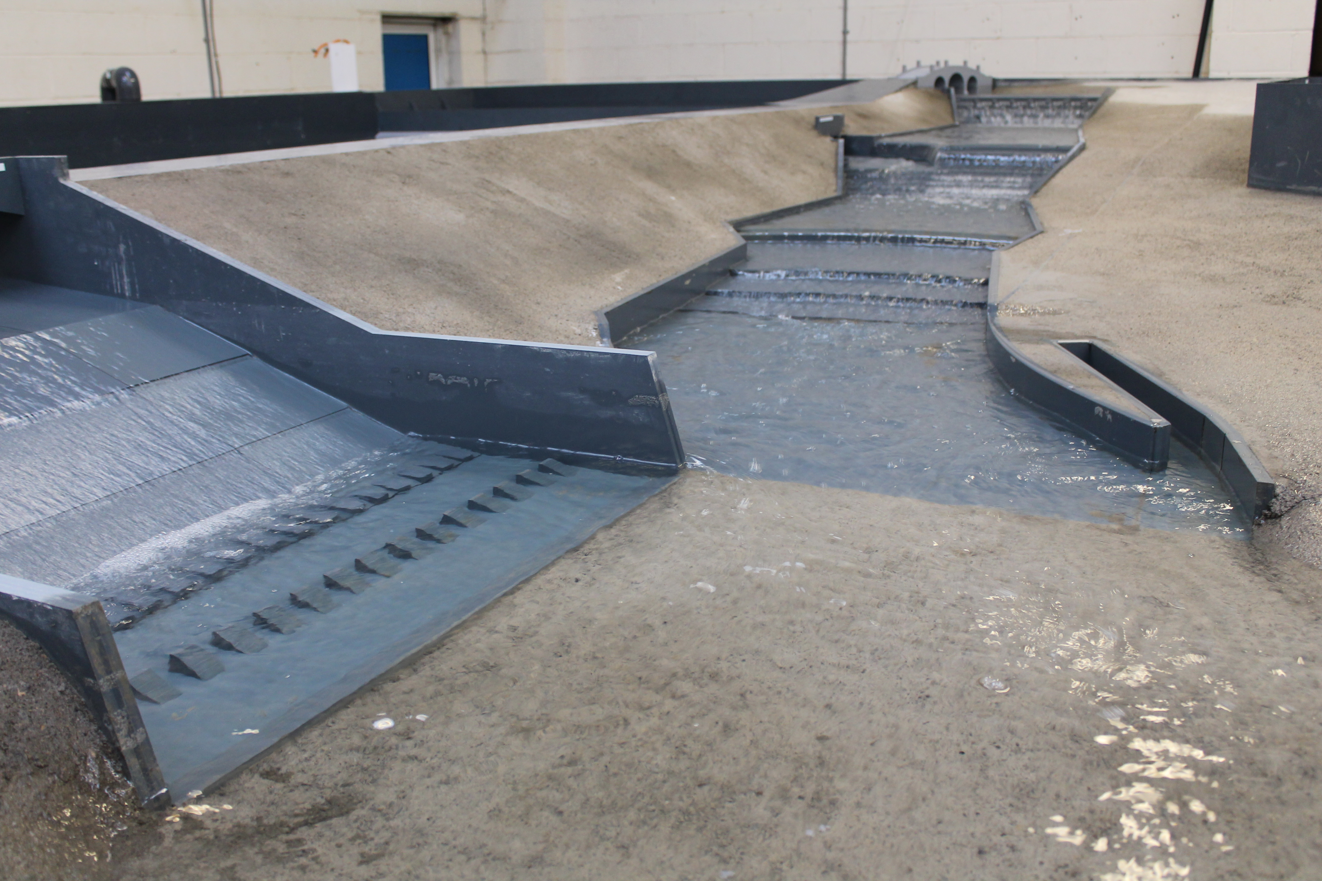
An inspection of the embankment, spillways, culvert, cascade and channel beds and associated side walls was undertaken by the Inspecting Engineer under Section 10 of the Reservoirs Act 1975 and a number of serious safety concerns over the capacity and condition of the cascade were raised. In addition, a number of improvements / repairs were proposed to both the embankment, both spillways, the cascades and both the channel bed and side walls.
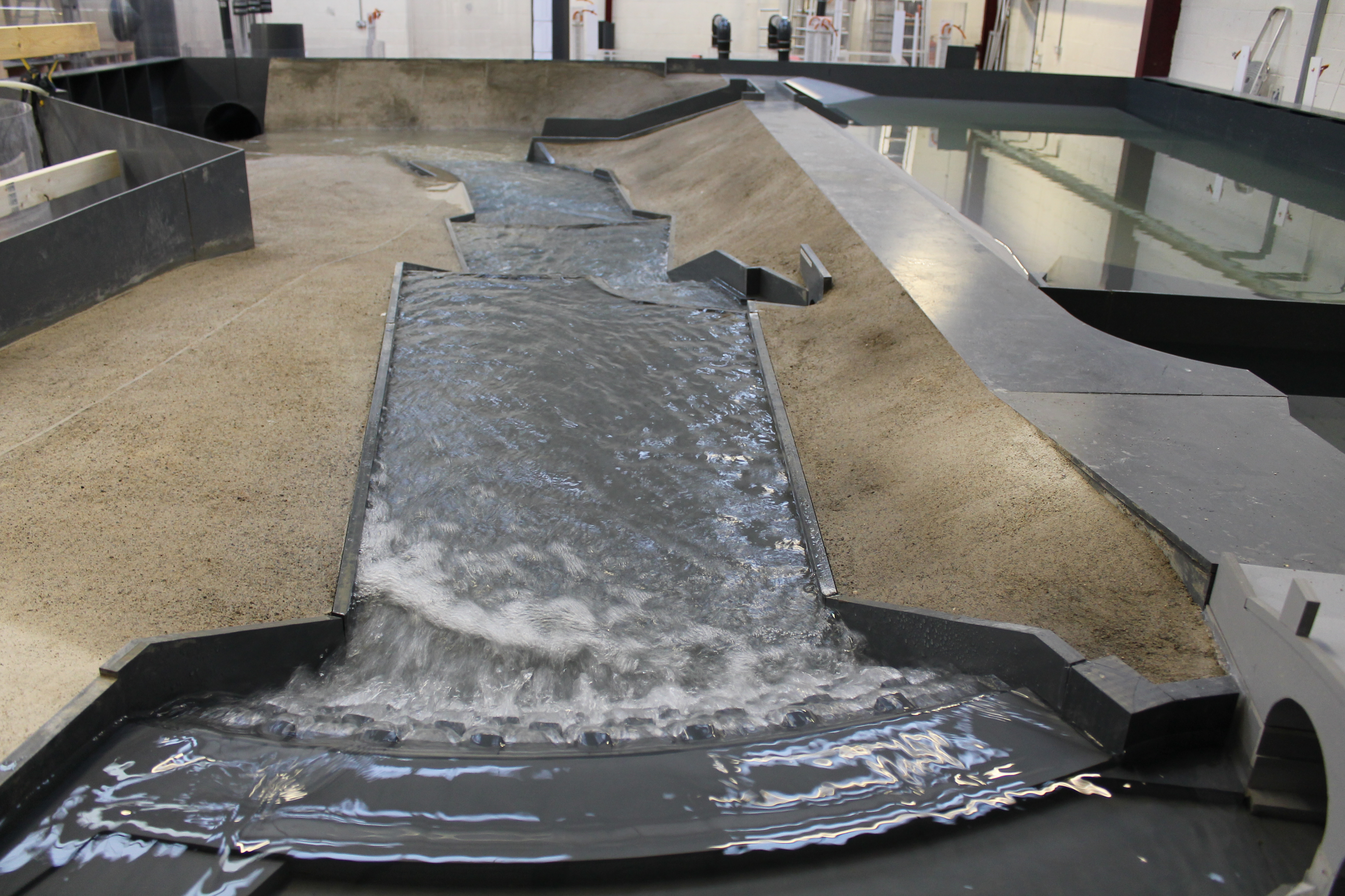
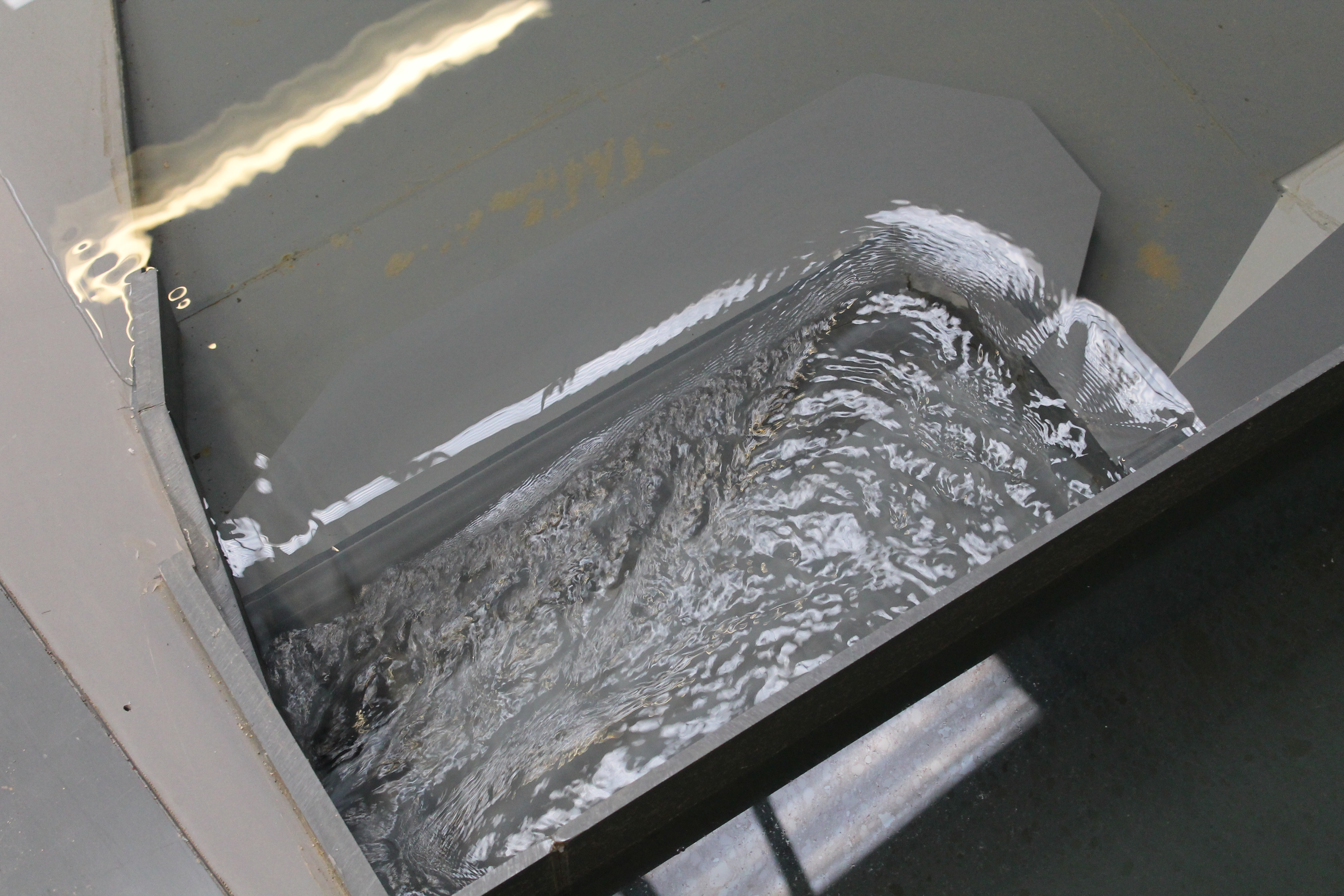
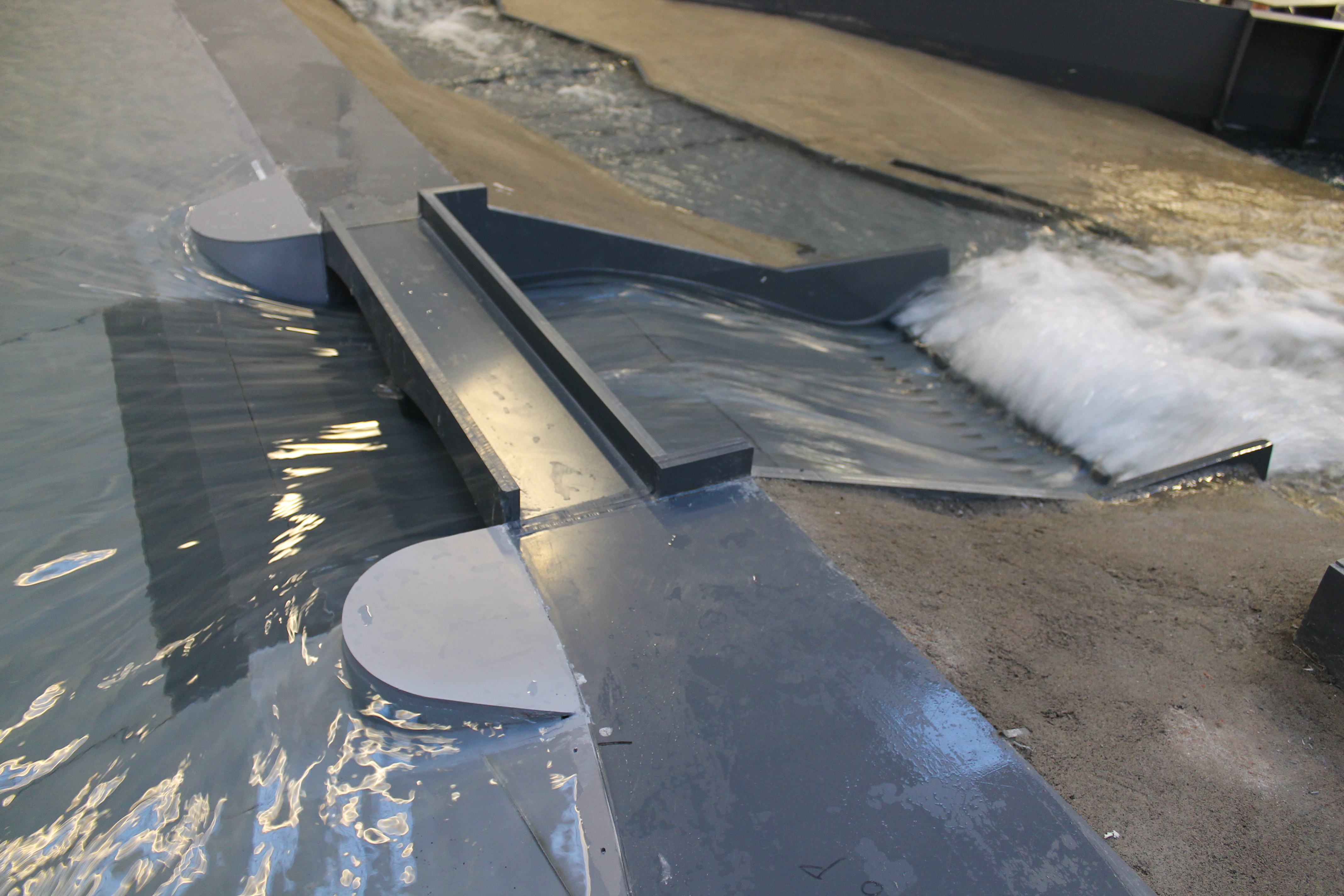
A series of studies were undertaken to determine the hydraulic performance of the various spillways and cascades and to determine the inflow design flood, based on the PMF. One element of this study was the construction and testing of a physical hydraulic model to determine capacity of the two spillways, the flow split during high storm periods and the influence on the downstream system (i.e., out of channel flow / over-splashing), during a range of discharges.
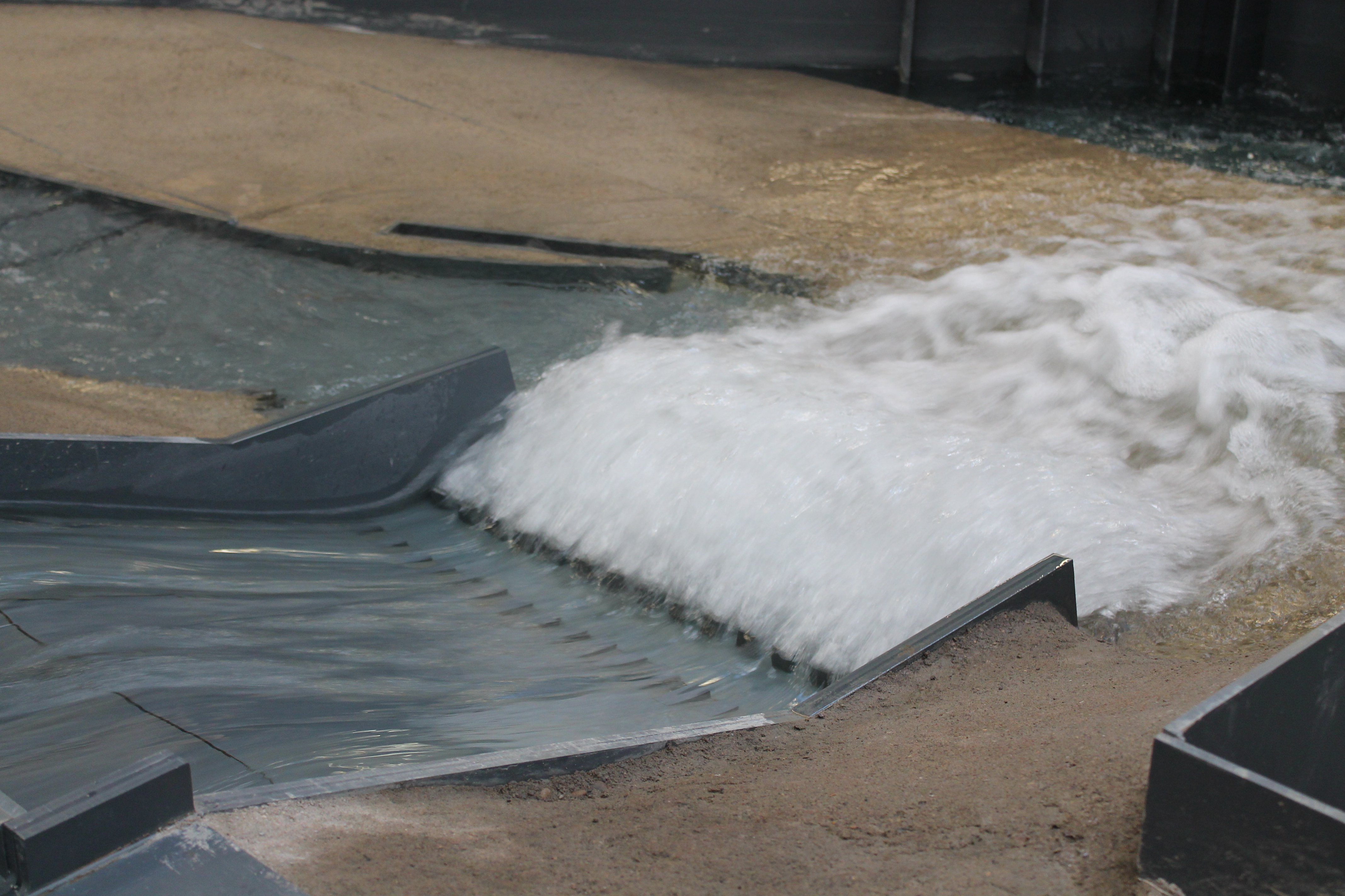
The model demonstrated that the spillways could not deliver the predicted PMF flows and hence, development was undertaken on the model to improve the discharge from both the Main and Original spillways. Further development within the cascade was undertaken to eliminate zones of known scour and localised increases in the guide wall elevations along the toe of the embankment to negate any potential for erosion of the embankment. Velocity vectors and peak water elevations were determined for a range of flows to establish the potential for future scour and out of channel flow.
An analysis of the developed arrangement demonstrated that the PMF flow could be contained within the reservoir without over-topping the embankment. Improvements to the Main and Original Spillways were sufficient to increase the discharge efficiency sufficiently to overcome the initial deficit. Reductions in channel velocity in areas known to be subject to scour were reduced sufficiently to negate erosion and determination of the required minimum increases to the cascade coping levels ensured protection of the embankment was maintained.
Moorfield Estate
Yeadon
Leeds LS19 7YA
e: info@hydrotecltd.co.uk
w: hydrotecltd.co.uk

