DUNMURRY WASTE WATER TREATMENT WORKS
Client: NORTHERN IRELAND WATERScale: N/A
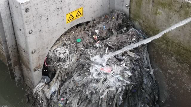
The CSO facility is part of the Dunmurry Wastewater Treatment Works located in Dunmurry NorthernIreland. The intention of this CFD analysis is to determine the contributing factor to an observed excessive buildup of screenings at the discharge end of the facility’s overflow screening system. The screen system is a Huber Technology model RoK2/700/6 with a rotating auger that is intended to keep its screen clear of debris.
The screenings have accumulated to the point where they have bound up the system and damaged the auger mechanism causing it to fail.
Subsequent results from the CFD analysis indicated that two characteristics of flow within the basin were identified as the primary source of the debris buildup.
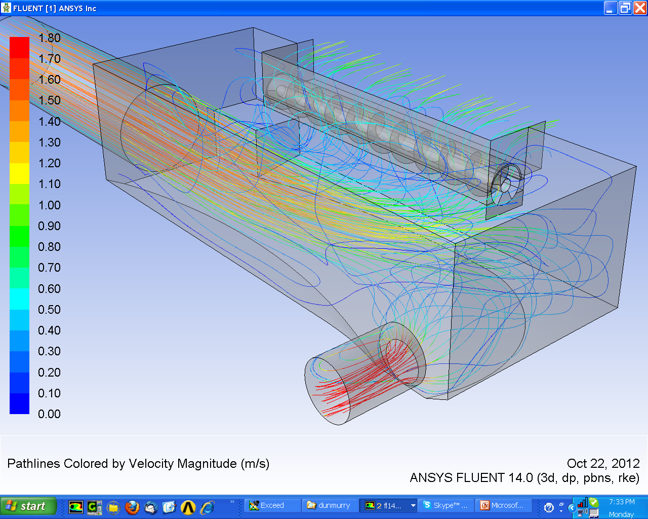
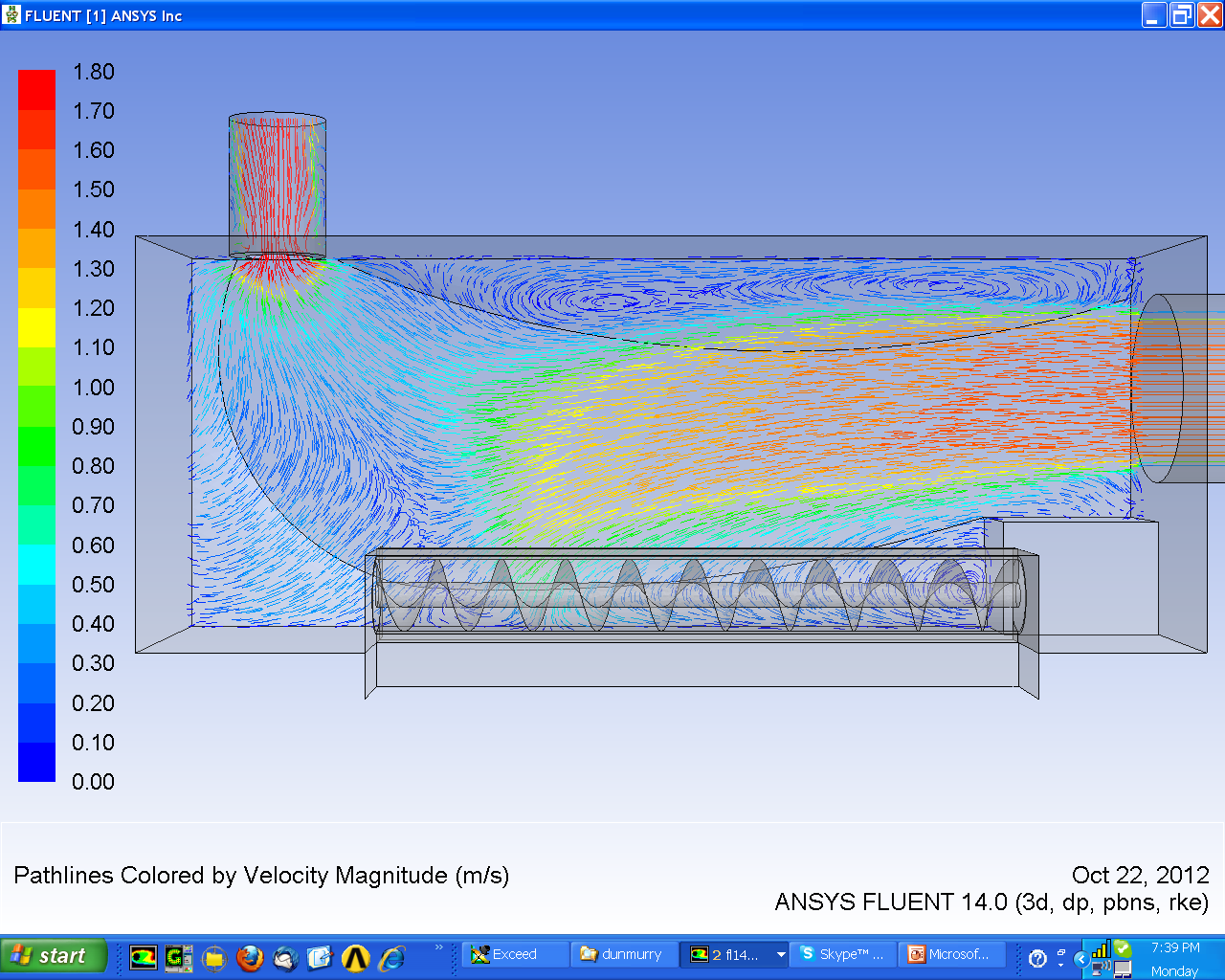
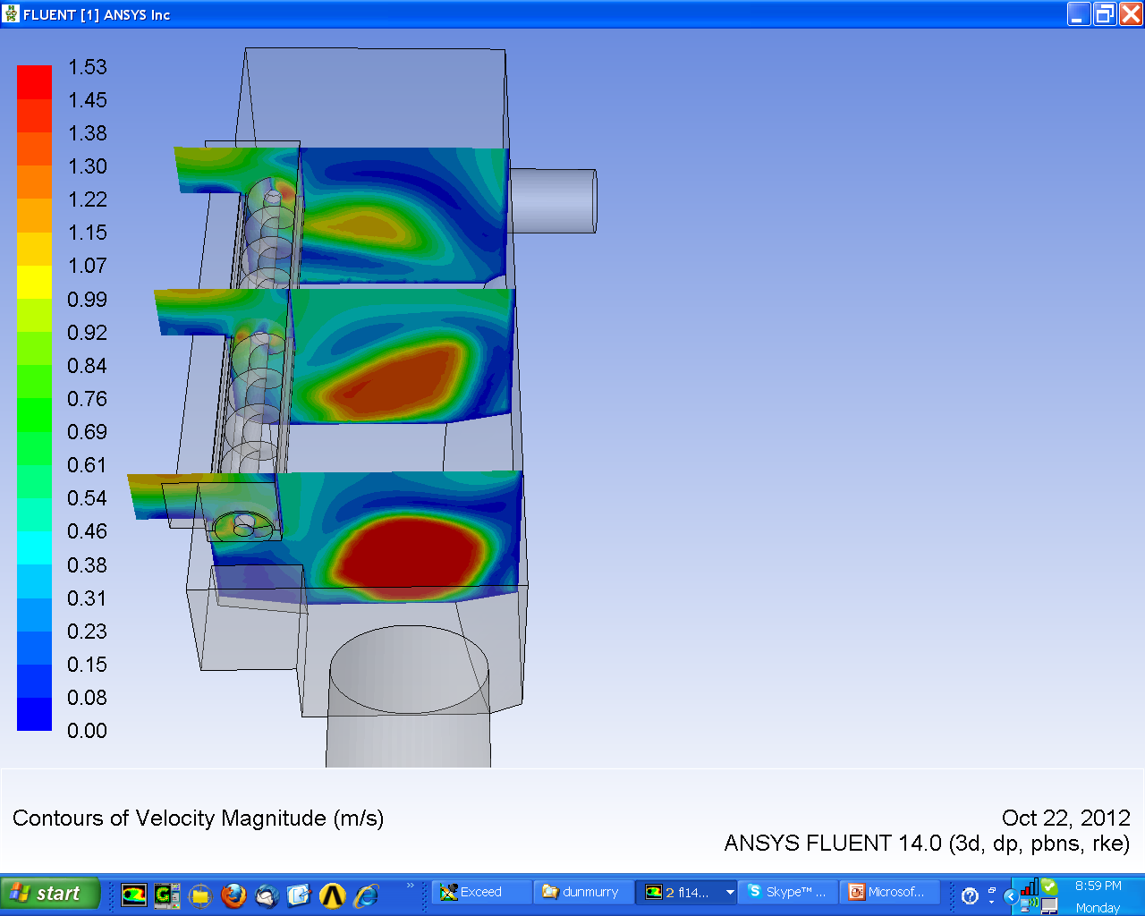
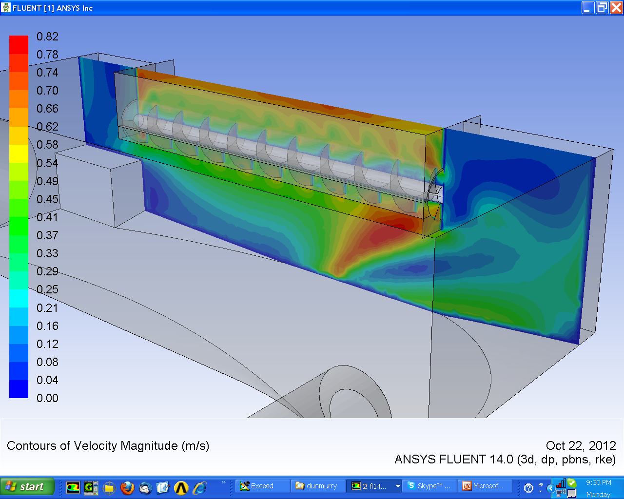
The behaviour of the jet formed by the flow entering the CSO basin was considered detrimental to an even velocity profile at the screen face. At design flow rates, 70 percent of the flow entering the basin passed through the Huber screen system and over the overflow weir thus skewing the inflow jet to one side towards the screen. This resulted in the jet impinging on the discharge end of the auger in the screen system.
The associated higher component of velocities at the downstream section of the screen system was considered to be problematic in terms of denying the attached screenings release. Over a prolonged period of a storm event, continual impaction of screenings to the observed high velocity zone with little removal could potentially cause significant buildup with little release.
In addition the CFD analysis observed a recirculation zone at the point of the auger discharge. This recirculation zone extends from the water surface down to the invert of the screen system assembly. The presence of the recirculation zone could lead to the screenings discharged by the auger remaining local discharge point without being readily cleared downstream. This issue is exacerbated by a flow that is entering the screen system via the auger discharge opening. The consequence of this return flow could be considered that screenings discharged by the auger are fed right back in to the area of its last spiral as such, local to the high velocity impact zone further compounding screening buildup and accumulation.
A change to the geometry of the screening system that is economical and relatively simple to construct was tested in a further CFD simulation. The modification consisted of a 1.2m long baffle plate positioned against the screen assembly at the auger discharge location. The baffle extended from the water surface down to a depth even with the base of the screen assembly.
According to the results from the CFD simulations, the addition of a baffle to the discharge end of the screening assembly could help re-distribute the loading of debris on the screen. With the debris loading distributed more evenly on the screen, the auger mechanism should operate more efficiently and be able to clear debris from the exit more readily.
Additional benefit of the suggested baffle was the suppression of the noted re-circulation zone located at the discharge end of the auger. By supressing the area of re-circulation or alternatively re-locating the re-circulation zone away from the auger exit, screenings exiting will be transported sufficiently away that re-presentation is unlikely to occur. It is considered that no more improvement or understanding could be gained by anymore CFD iterations.


