


SANTIAGO WWTW - FLOW DISTRIBUTION
Client: DEGREMONT SA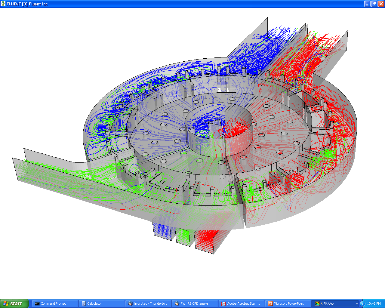

A major expansion of the existing Waste Water Treatments Works in Santiago, Chileis proposed. The existing works currently has a capacity of 4.40 m3/s. Under Phase One the proposed refurbishment this will rise initially by 2.20 m3/s to 6.60 m3/s followed by a further rise of 2.20 m3/s under Phase Two to 8.80 m3/s. Under Phase Three of the work the eventual future treatment capacity will be 11.00 m3/s, however, a peak flow capacity of 19.50 m3/s has to be considered.
As part of the expansion a multi-level flow distribution chamber is proposed downstream of the grit chambers to distribute flows between downstream treatment trains. Two options are to be considered.
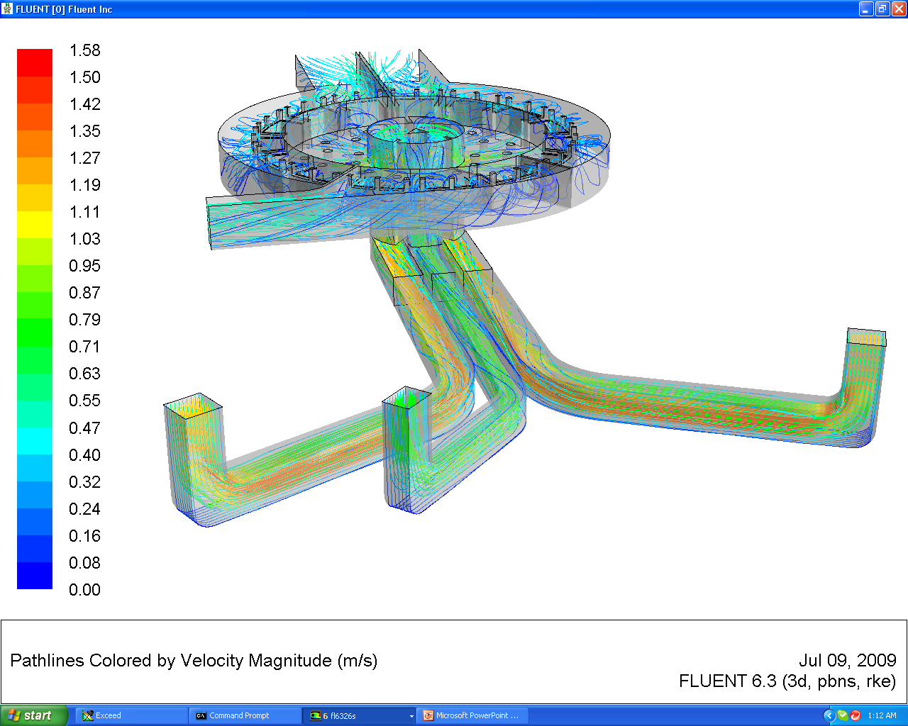
Option One will comprise of two parallel, low level, inlet ducts. Each duct will include stop logs in communication with a common chamber for interconnection or isolation. The inflow will feed into a second level, semi-circular split stilling chamber, for flow stabilisation. The third and final level circular chamber is split into three sections. The first section is equipped with three weir boxes, while the second and third are each equipped with six weir boxes. Each weir box will included individual stop logs to enable isolation of the respective treatment trains. Each of the fifteen weir boxes are similar and comprise four 2.0 m long weirs, with a total of sixty weirs and sixty corresponding stop logs.
Option Two is similar to Option One, however, flow is introduced into the distribution structure via three parallel, low level, inlet ducts. The discharge arrangement will be similar to Option One.
Option Two is similar to Option One, however, flow is introduced into the distribution structure via three parallel, low level, inlet ducts. The discharge arrangement will be similar to Option One.
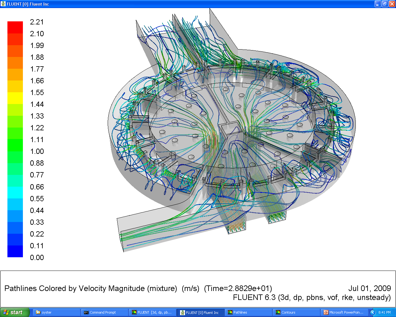
To study the performance of both options, the client has commissioned a Computational Fluid Dynamic (CFD) study. The study will initially consider the performance of both Options One and Two when operating at the peak flow of 19.50 m3/s to determine if one option provides a more favourable presentation of flow to the three discharge chambers and ultimately the fifteen weir boxes.
While the analysis had shown that outlet train Q5 was receiving too much flow, it was considered that overall the flow distribution chamber was working quite well for an extreme and possibly infrequent event with Option Two performing slightly better than Option One.
Following discussions with the client, Option One with the twin inlet trains is the preferred option due to reduced civil costs. In addition the position of the isolating penstocks and stop logs in the inlet are to be revised to ease access during maintenance.
Therefore, further analysis was undertaken on a two inlet stream arrangement with revised penstock positions. The analysis considered a total inflow of 8.80 m3/s with the flow apportioned equally between the inflow trains Q1 and Q2. Outflow streams Q3 and Q4 were open with outlet Q5 closed. For the purposes of the report the revised arrangement is designated Option 1B.
Analysis of Option 1B
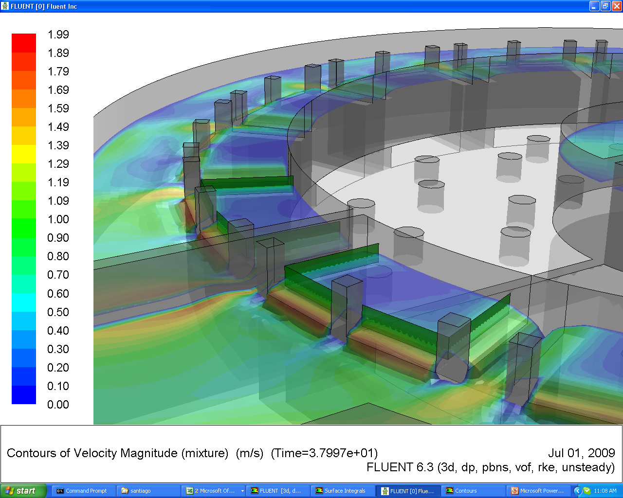
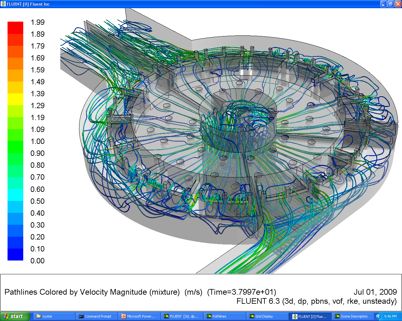
While the flow distribution to the duty weirs varied in some cases between +22% and -25%, flow was apportioned almost equally between the two outlet trains with flow on approach to the flumes relatively uniform. This would ensure stable operation of the flumes. The analysis had shown that Option 1B worked very well at an inflow of 8.80 m3/s.
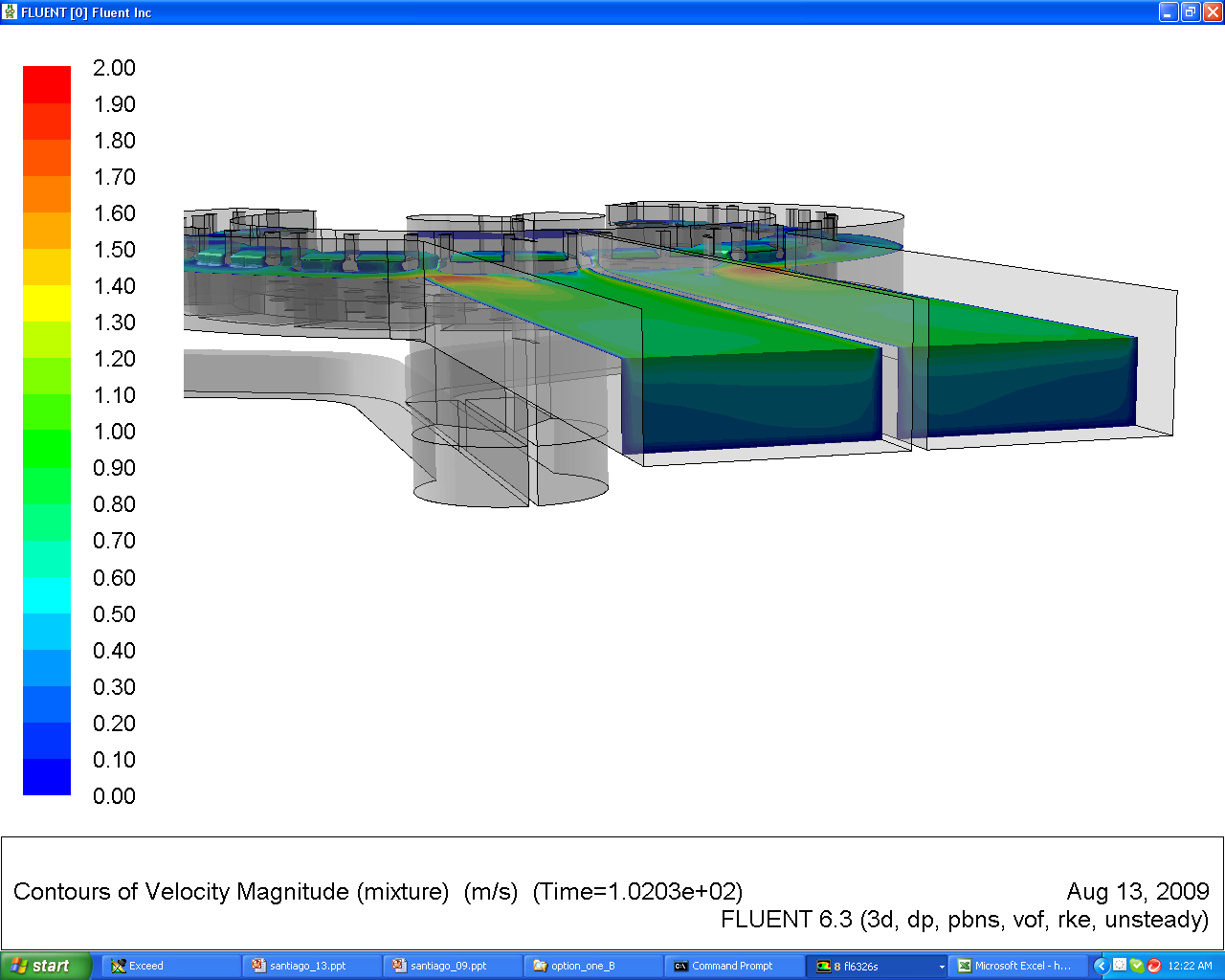
The scope of the analysis was extended to consider any potential for free surface vortex formation at the entry to the inlet trains. Strong, coherent vorticity could lead to instability in the performance of the system due to entrained air being drawn into the inlet trains which in turn would increase head losses.
Each inlet is located in a common channel which is fed via eight outlet ports. As a starting point for the analysis all eight ports were assumed to be open with each outlet discharging 1.10m3/s, 8.80 m3/s in total, into the common channel. Under these conditions no vortex formation was predicted.
However, we are unsure as to the potential operating combinations of the outlets, i.e. can one or more outlets be closed and at what flows. Under these conditions asymmetry of flow generated on approach to the inlets could initiate the mechsiam for vorticity. We would recommend that further analysis of the outlet channel is considered if the possibility exists for one or more outlets to be closed.
Moorfield Estate
Yeadon
Leeds LS19 7YA
e: info@hydrotecltd.co.uk
w: hydrotecltd.co.uk

