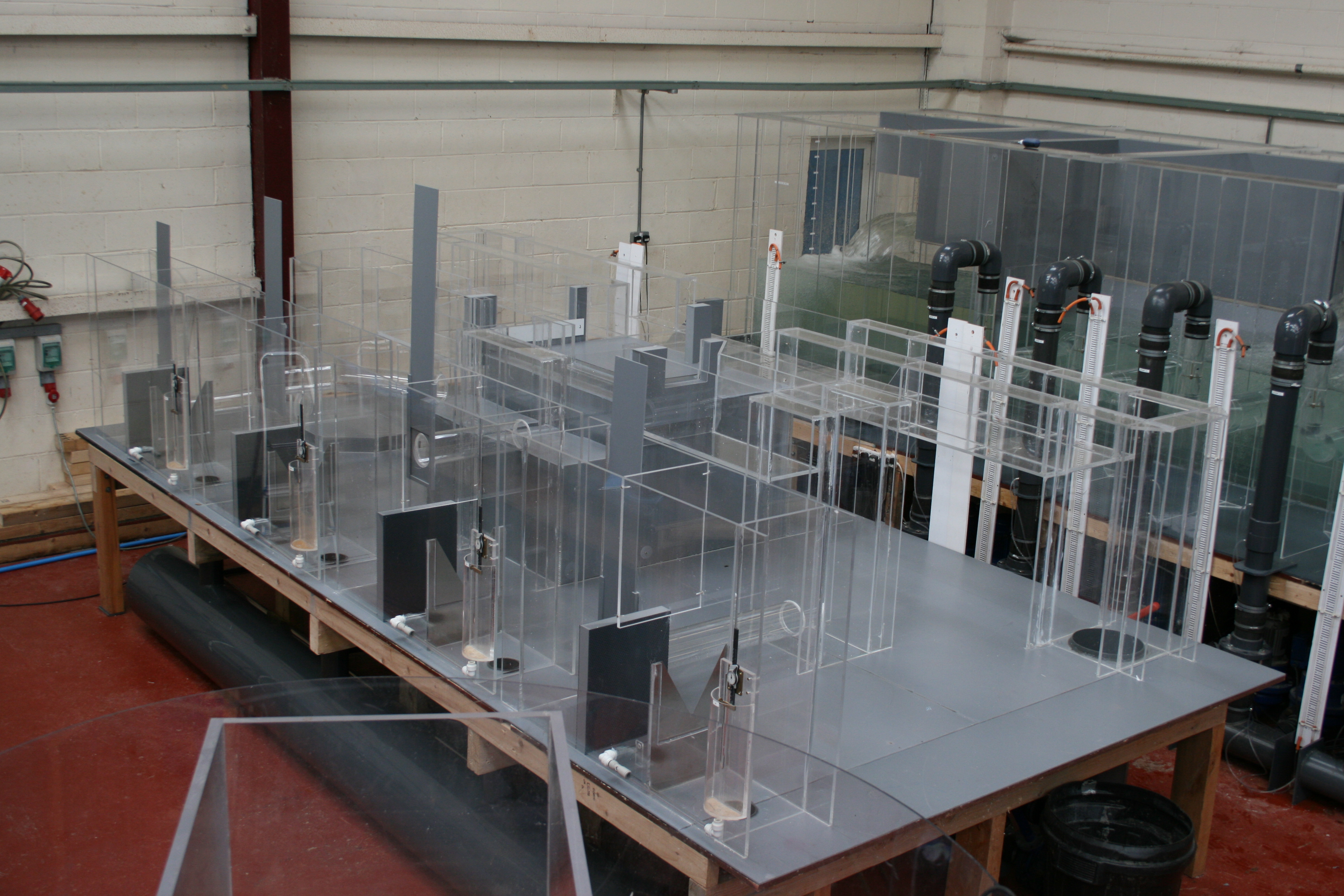
Rossendale Humus Tanks
Client: UNITED UTILITIESScale: 1/4th
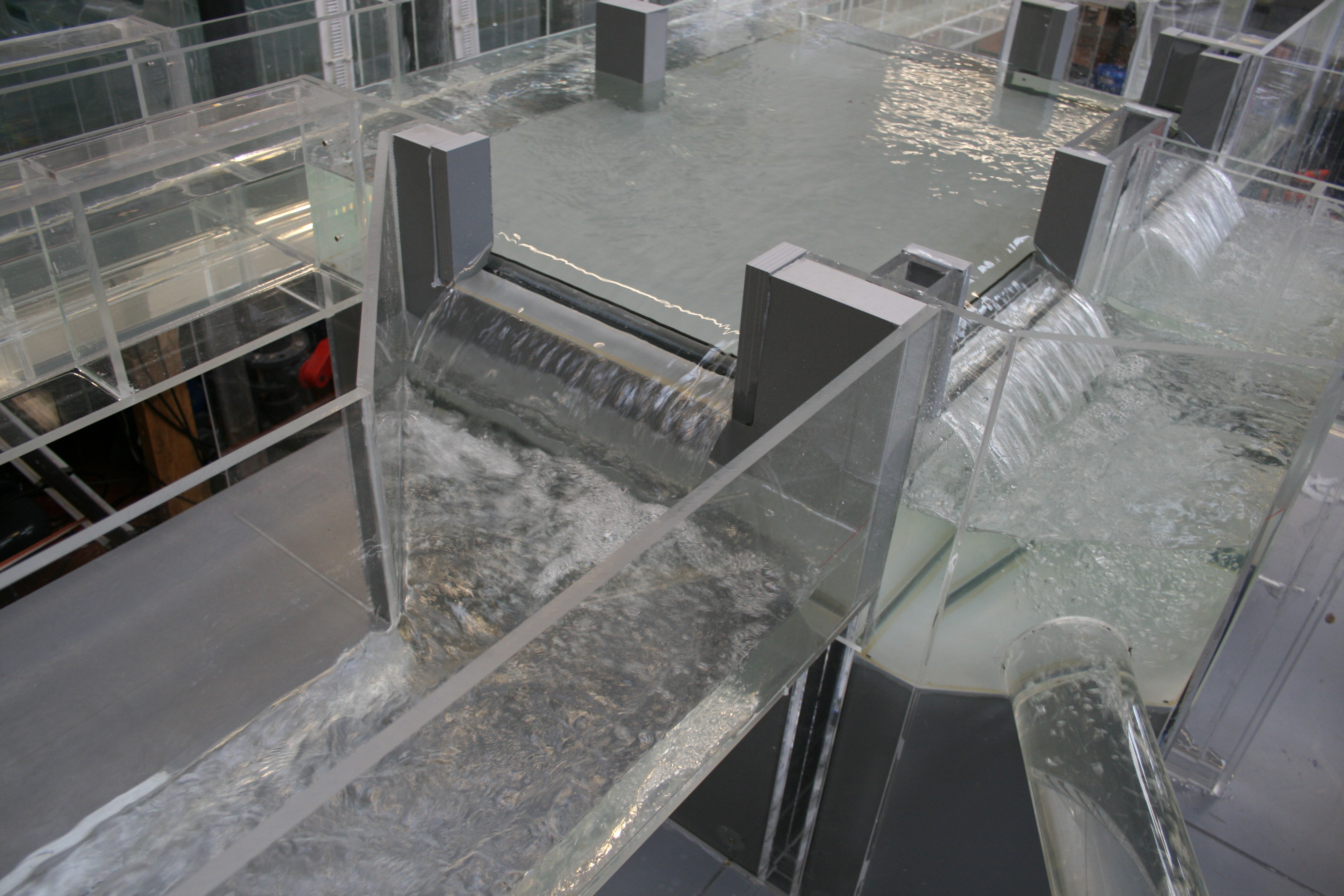
The Rossendale Humus Tanks are notorious for poor flow distribution to the existing Tanks, under a period of refurbishment an additional Humus Tank will be installed centrally between the existing sets of three. Under the refurbishment the existing distribution chamber will be modified to incorporate the additionalHumusTank and provide improved flow division.
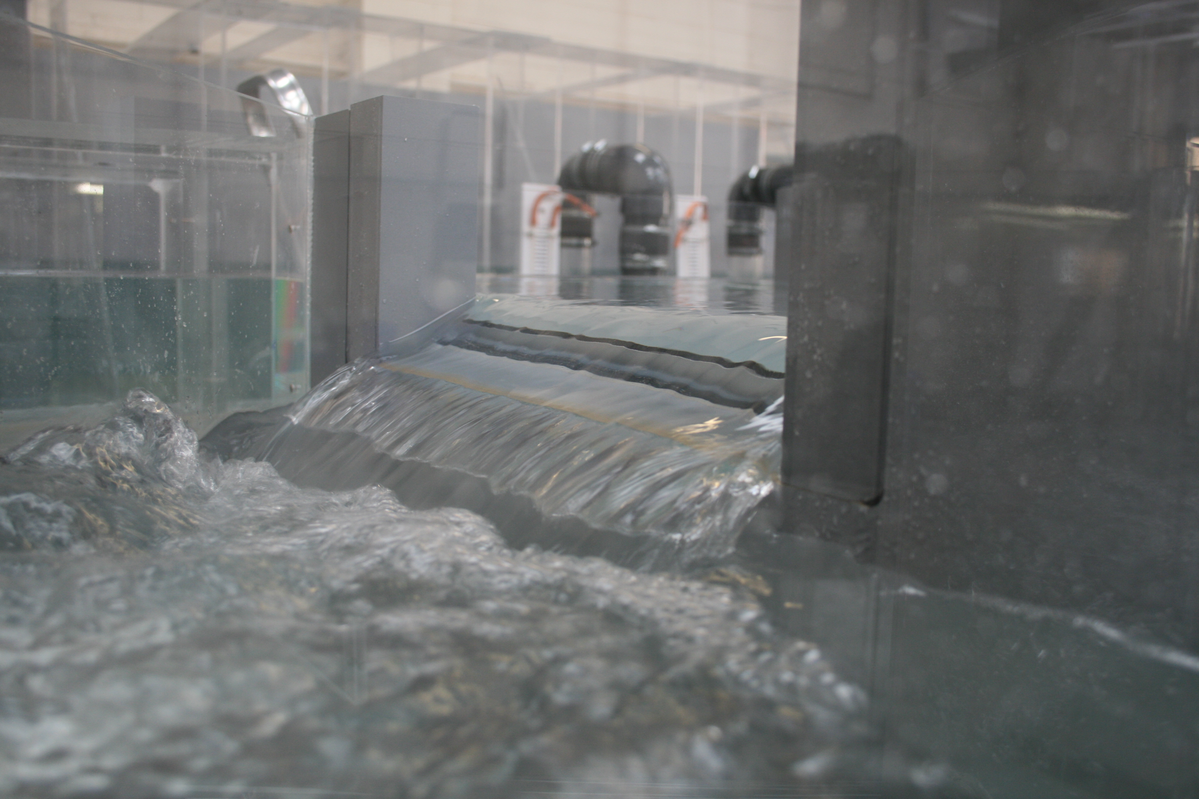
The flow distribution chambers will include four weirs all at various sizes to discharge the required flow to each Humus Tank. Within the distribution chambers, two weirs are considerably smaller in length, approximately, half the size of the others, to split the flow equally, feeding the new additional Humus Tank seven. Operation will allow the required flow to be discharged over the reduced size weir transporting half the required flow from each distribution chamber to the new Humus Tank, this will be replicated on an identical distribution chamber, as such, the new Humus Tank will receive the required flow.
The proposed distribution to the 7 number Rossendale Humus Tanks are by two mirror image distribution chambers, linked by a long inlet channel. The two chambers are represented by a single physical model, modified to take account of asymmetry of inflow and link channel geometry asymmetry. The Client has advised that the design is to distribute flows to the Humus Tanks in proportion to tank area. The Client has used HADES, a mathematical model, to predict the flows in the link channel for normal operation and selection of maintenance cases with one Humus Tank out of service.
Both of the two distributing chambers will experience different approach conditions regarding flow split and channel width, subsequently the weir sizes are not comparable.
Hydraulic guides recommend an average flow split not exceeding +/- 5% variation from the flow distribution in proportion to Tank area when operating at the full flow to treatment of 840 l/s. To ensure the flow splits and required discharge are maintained, a physical model study was proposed to determine the performance of the flow distribution and discharge rate, and, if found necessary, develop modifications to improve the general performance.
Distribution Chamber 1
Testing verified the design of the Rossendale Humus Tanks distribution chamber 1, following the incorporation of a relatively minor increase in weir length on weir 3. The variation in flow distribution and discharge to the weirs was well within the specified range at approximately +/- 5% of the mean value throughout the anticipated operating range, with the recorded discharge in the main very close to the stipulated values.
The distribution performance deteriorated marginally with any one weir out of service, this variation was attributed to an inherent sensitivity of the chamber arrangement. It was considered that the proposed chamber arrangement provided an economic and efficient design, whereby good flow distribution was achieved within a small plan area at shallow depth following the incorporation of a relatively minor increase in weir length.
It was considered that further improvement in flow division would not be achieved without significant changes to the outlying geometry of the chamber for example deepening the distribution forebay.
Distribution Chamber 2
The second phase of testing studied the second distribution chamber, (chamber 2). Chamber 2 was a mirror image of the first distribution chamber however, the inlet channel had reduced in width from 1.150 m to 0.750 m. The associated flow split from the inlet channel also altered to 240 l/s and 180 l/s respectively. Testing was required to determine as per earlier testing, what modifications, if any, were required to achieve an acceptable discharge of flow over the associated weirs within distribution chamber 2.
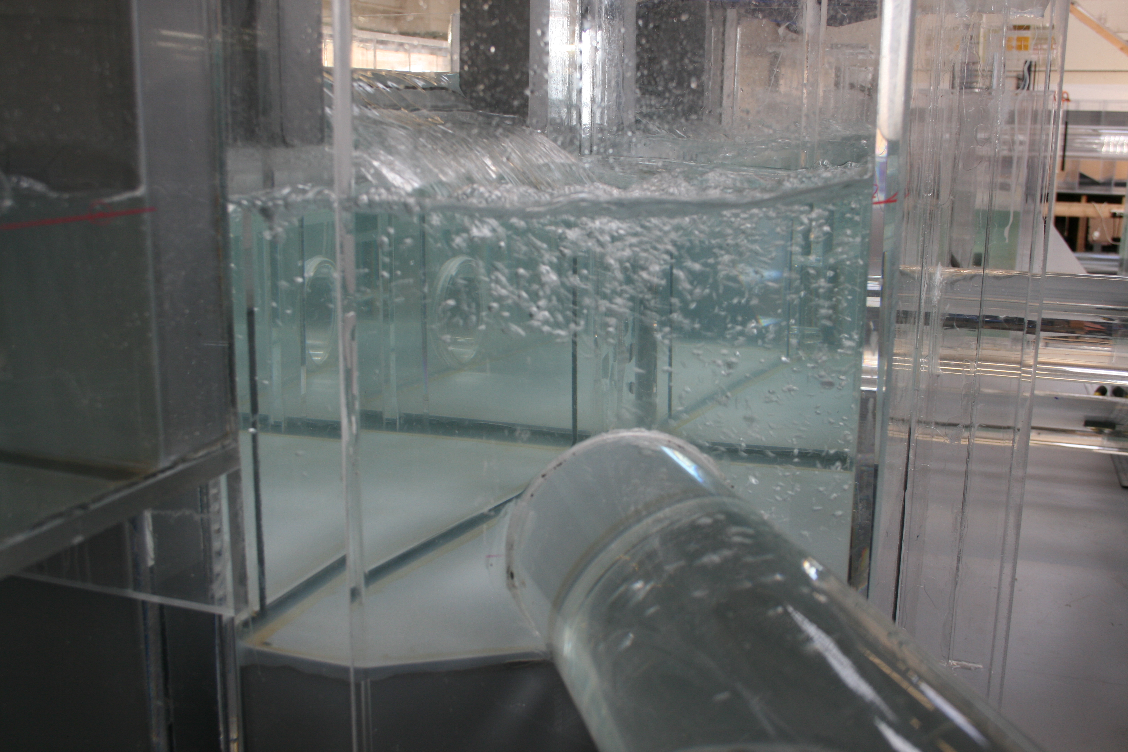
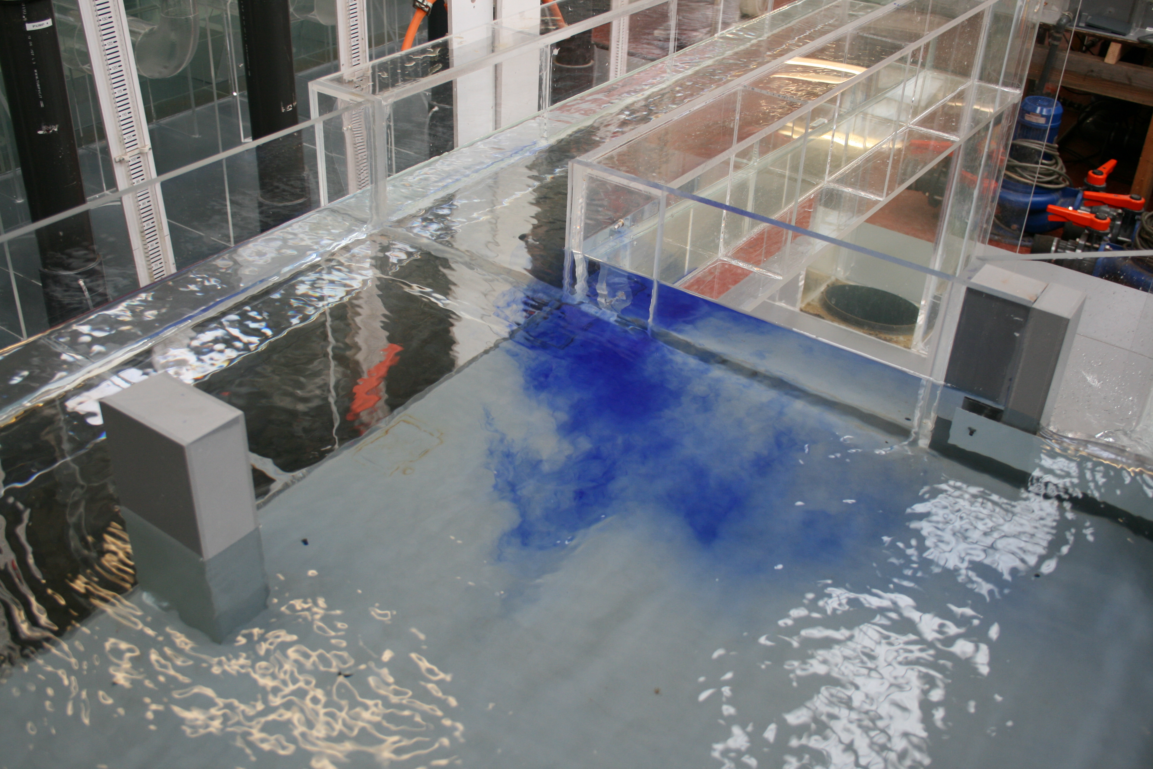
The flow split on approach to the distribution chamber exhibited a less severe flow bias, resulting in a bi-directional rotating flow path to adjacent sides of the distribution forebay, operating in a clockwise and anti clockwise direction dependant on weir designation. The overlying flow path produced a significant flow surplus to weirs 7B and 6 of plus 12.2 and plus 9.4 respectively with unacceptable deficits to the central weirs, this was attributed to the observed flow paths directing the majority of inflow to the associated weirs.
The development programme studied lengthening the central weirs HT4 and HT5 to encourage more flow discharge. The weirs were both increased to 1.440 m, some 30 mm increase in length. We would suggest the weir plates are reduced by 15 mm either end to ensure a symmetrical profile is maintained.
The results indicated that the recorded distribution was within the specified limit of +/- 5% of the mean value stipulated as acceptable distribution and discharge between the weirs. The slight increase in weir length on the central weirs HT4 and HT5 further enhanced the required discharge by allowing a greater proportion of flow to be discharged by the associated weirs, this in turn slightly deprived weirs HT6 and HT7B producing the required discharge to be within the stipulated +/- 5%.


