


K Phase III and SWRO Pumping Stations
Client: ABJV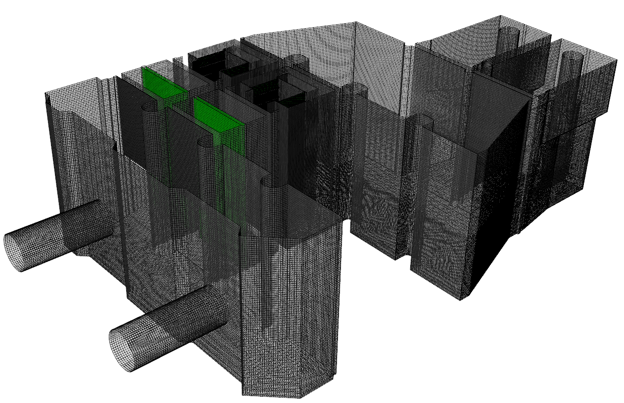
Scale: N/A
This summary covers the CFD model assessment undertaken on the SWRO and K‑Phase‑III seawater intake pumping stations. The following sections of the summary briefly describe the findings detailed in this report
CFD Modelling Methodology
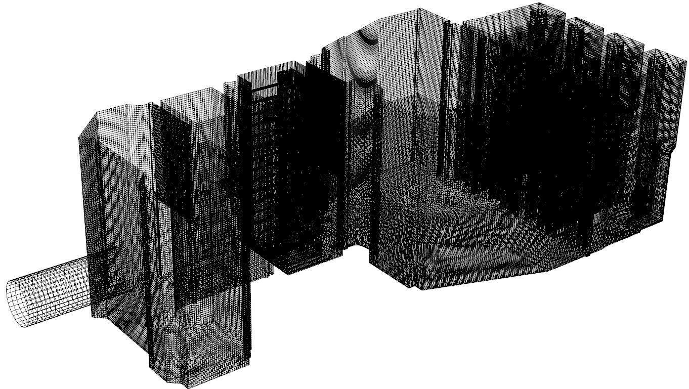
ABJV’s drawings were rendered into two 3D models (K-Phase III and SWRO separately), the 3D models were meshed into individual cells, for which the Navier-Stokes equations were solved numerically. The modelling specifically solved the K-ε turbulence model equations for each individual mesh cell. The modelling was conducted utilising the commercial ANSYS Fluent 19.2 solver.
CFD modelling is useful as it can give accurate predictions of general flow patterns and operating conditions, however the standard (ANSI/HI 9.8-2012) makes the following statements regarding the accuracy of using it to assess pump intake conditions.
SWRO
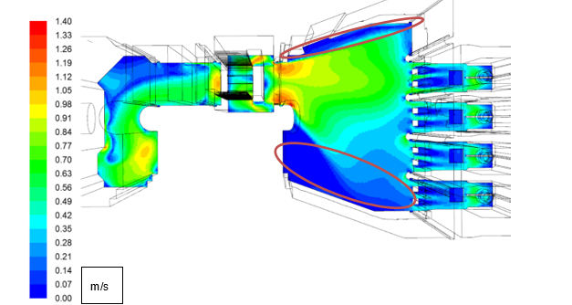
In Summary, the performance of the station was deemed good, with the pumping environment devoid of any evidence of vorticity penetrating through to the pump suctions, with the pump units characterised by low pre-swirl rotation. Testing did however conclude that, the pump units did demonstrate unacceptable velocity distribution (in line with the ANSI standards), although in our considered opinion the symmetry of the velocity distribution observed under all test scenarios, indicated that this would not be severely detrimental to pump performance. Confirmation of the acceptability of these findings would have to be provided by the pump supplier. The pumping station could also be potentially susceptible to minor areas of deposition and accumulation of settleable solids within the forebay, however, this is dependent on the solids concentration of the influent and may not be considered an area for concern.
Proposed Modifications
Following the initial review, numerous options were found necessary to mitigate the issues local to the pump units. It was considered that the following proposals would improve the pumping environment within the station.
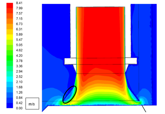
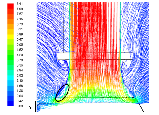
Suction cone and single element vane – The programme of development recommended reducing the width of the single element vane to the thickness of plate steel i.e. approximately 10 mm to reduce the potential wake behind the vane. In addition to the alterations to the vane, it was proposed that a 30o suction cone was installed beneath the pump to aid the flow transition from horizontal flow within the sump to vertical flow in the discharge pipe. The flow attachment to the cone was designed to reduce the zone of flow separation at the leading tip of the pump impeller eye.
Final Assessment
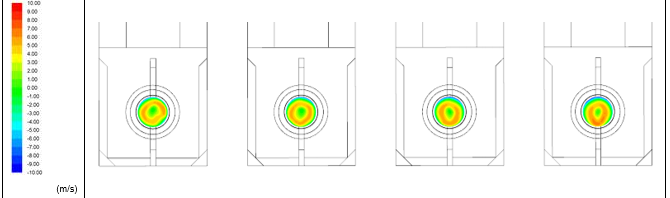
The proposed modifications mitigated against the previously observed low velocity zone at the tip of the pump impeller plane. Consequently, it was concluded that the flow conditions within the station were considered acceptable, with the CFD model evidencing low pre-swirl rotation and an environment devoid of free surface or sub-surface vorticity. Measurements along the pump impeller plane highlighted a low velocity zone downstream of the three suction vanes, with a peak negative distribution of -25.72 %, i.e. outside the allowable limits of ± 10 %, however these zones were radially symmetrical and part of a standardised pump design and therefore not deemed detrimental to performance. The velocity distribution measured directly downstream of the vanes all fell well within a range of ±5 % and therefore it was concluded that the pump would operate in acceptable conditions throughout.
The hydraulic grade line plotted through the station calculated the maximum upstream to downstream loss at 310 mm, this was not considered excessive.
K-Phase III
In summary, the performance of the station was deemed unacceptable, with the pumping environment potentially subject multiple adverse effects, including multiple submerged vortices and poor velocity distribution at the pump impeller plane. Testing did however conclude, that the screen channels were subject to an acceptable flow split, i.e. within ±5 %, at a maximum discrepancy of ±0.9 %. The velocity profile local to the invert of the station indicated that with duty rotation of the screen and pump units, any potential areas of settleable solids deposition that would likely occur would be cleared under a different mode of operation.
It was therefore, concluded to achieve an acceptable pumping environment, a programme of development will have to be undertaken, to improve hydraulic performance.
Proposed modifications
Following the initial review, numerous options were found necessary to mitigate the issues local to the pump units. It was considered that the following proposals would improve the pumping environment.
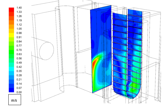
Profiled vane – Observations during the initial assessment determined that that there was a low velocity zone present in the central region of the pump impeller plane generated by the wake of the initially proposed single element vane arrangement. The profiled vane provides a sloped surface to allow for better flow attachment and reduced flow separation on entrance to the pump units.
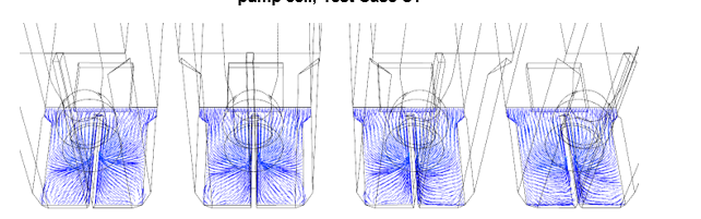
Flow training columns – Testing determined that flow entered Pump Cell P02 obliquely and instigated mass anti-clockwise-horizontal rotation. Consequently, flow straightening columns were proposed, comparable to the ones on the SWRO station. These columns were designed to constrict and straighten the flow, to generate more uniform approach flow to the operative pump units.
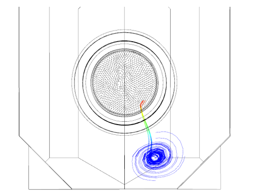
Side and rear 60o benching – The initial assessment demonstrated that the pump units could be subject to coherent sub-surface vorticity forming off the cell sidewalls and penetrating through to the pump impeller position. The proposed benching was designed to remove the vertical flat surfaces that can act as the formation point for submerged vorticity, preventing the formation of coherent vortex cores.
Final assessment
Following the assessment, the proposed modifications mitigated against the previously observed low velocity zone in the centre of the pump impeller plane and the sub-surface vorticity that formed off the pump cell sidewall. Consequently, it was concluded that the flow conditions upstream of the pump bellmouth were considered acceptable, with the CFD model evidencing low pre-swirl rotation and an environment devoid of vorticity. However, measurements on the pump impeller plane highlighted a low velocity zone local to the upstream tip of the impeller, with a peak negative distribution of -16.8 %, i.e. outside the allowable limits of ± 10 %, it was concluded that this was a function of the bellmouth shape and not the operating environment. The bellmouth design is outside of ABJV’s design scope and is therefore, determined to be outside of the scope of this report.
The hydraulic grade line plotted through the station calculated the maximum upstream to downstream loss at 297 mm, this was not considered excessive.
Moorfield Estate
Yeadon
Leeds LS19 7YA
e: info@hydrotecltd.co.uk
w: hydrotecltd.co.uk

