


- SOUTH JEDDAH - AL KHUMRA SCREEN CHAMBER AND PUMPING STATION
- BRA 3494 – Sabesp Sao Lourenco, High Pressure Pumping Station
- FRANKLEY DE-ALK TRANSFER PUMPING STATION
- Deephams FTFT Pumping Station and Inlet Culvert
- Riverside Sewage Treatment Works - Regional Sump 1
- La Villette Pumping Station
- Bewsey Bridge Pumping Station
- Suez Thermal Power Station - Intake Pumping Station
- Norway Road Pumping Station
- Grimonpont RAS Pumping Station
- Nab's Head Storm Inlet Channel and Storm Pumping Station
Pumping Stations
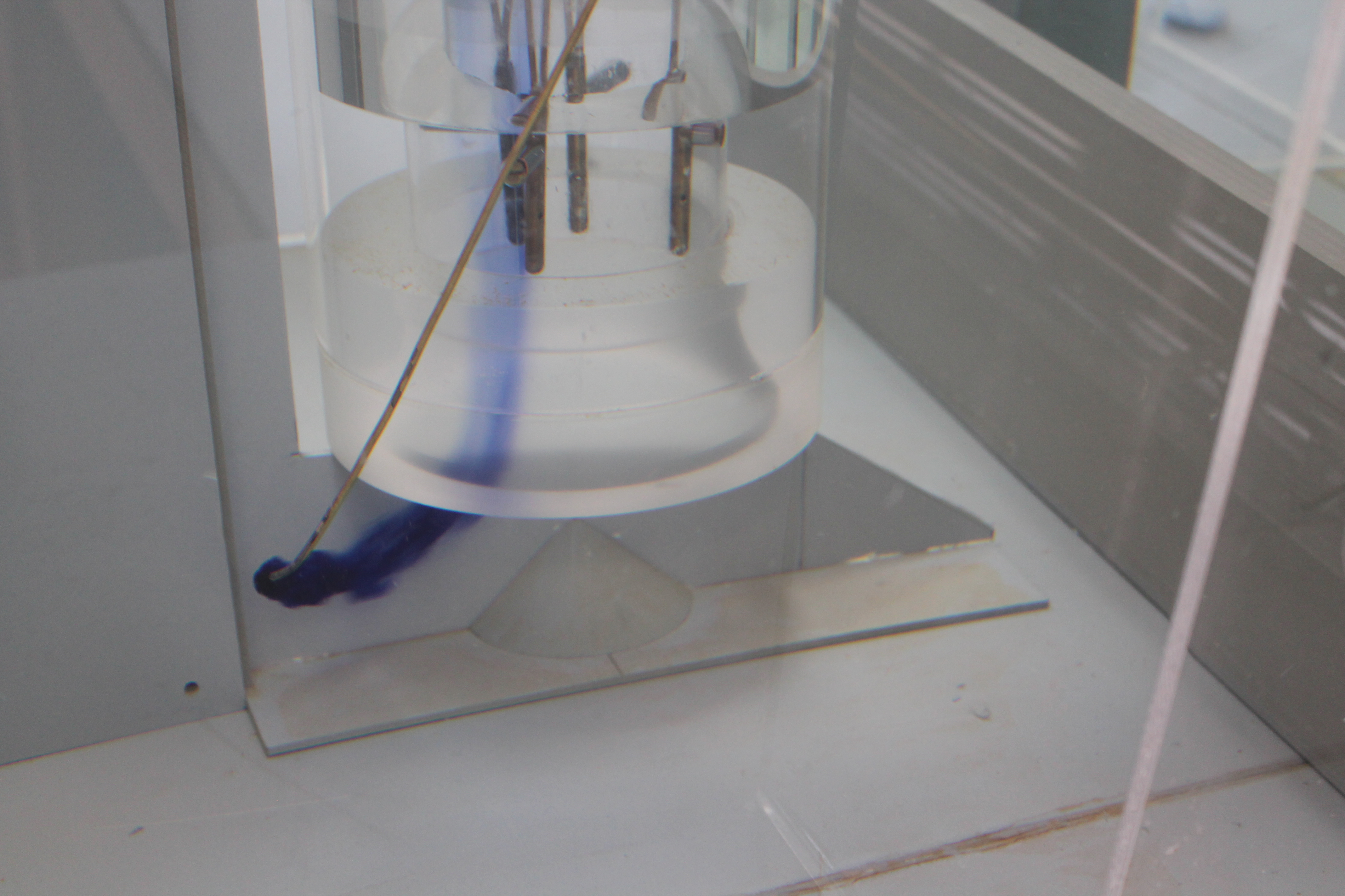
Grimonpont RAS Pumping Station
Client: Degremont Services SASU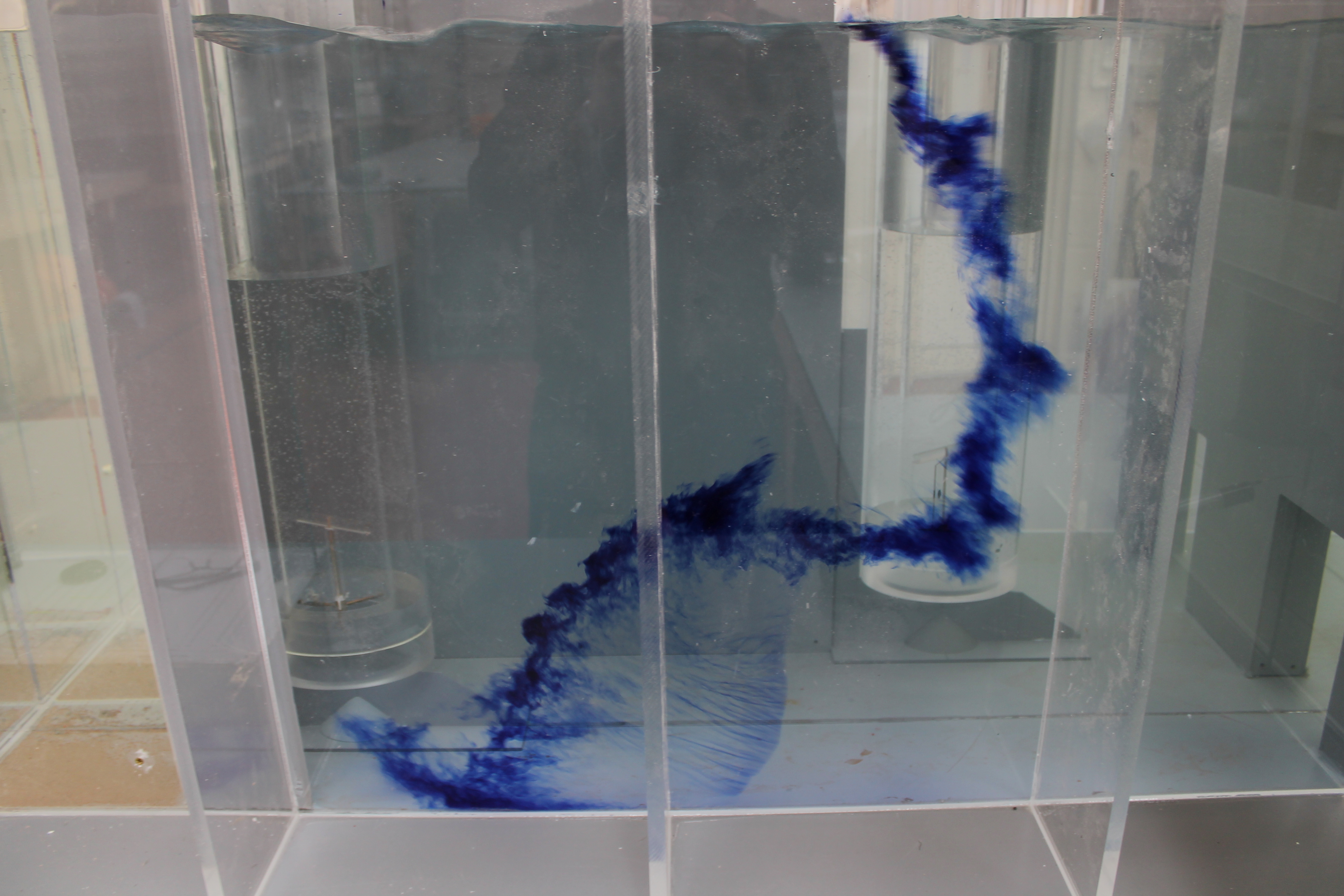
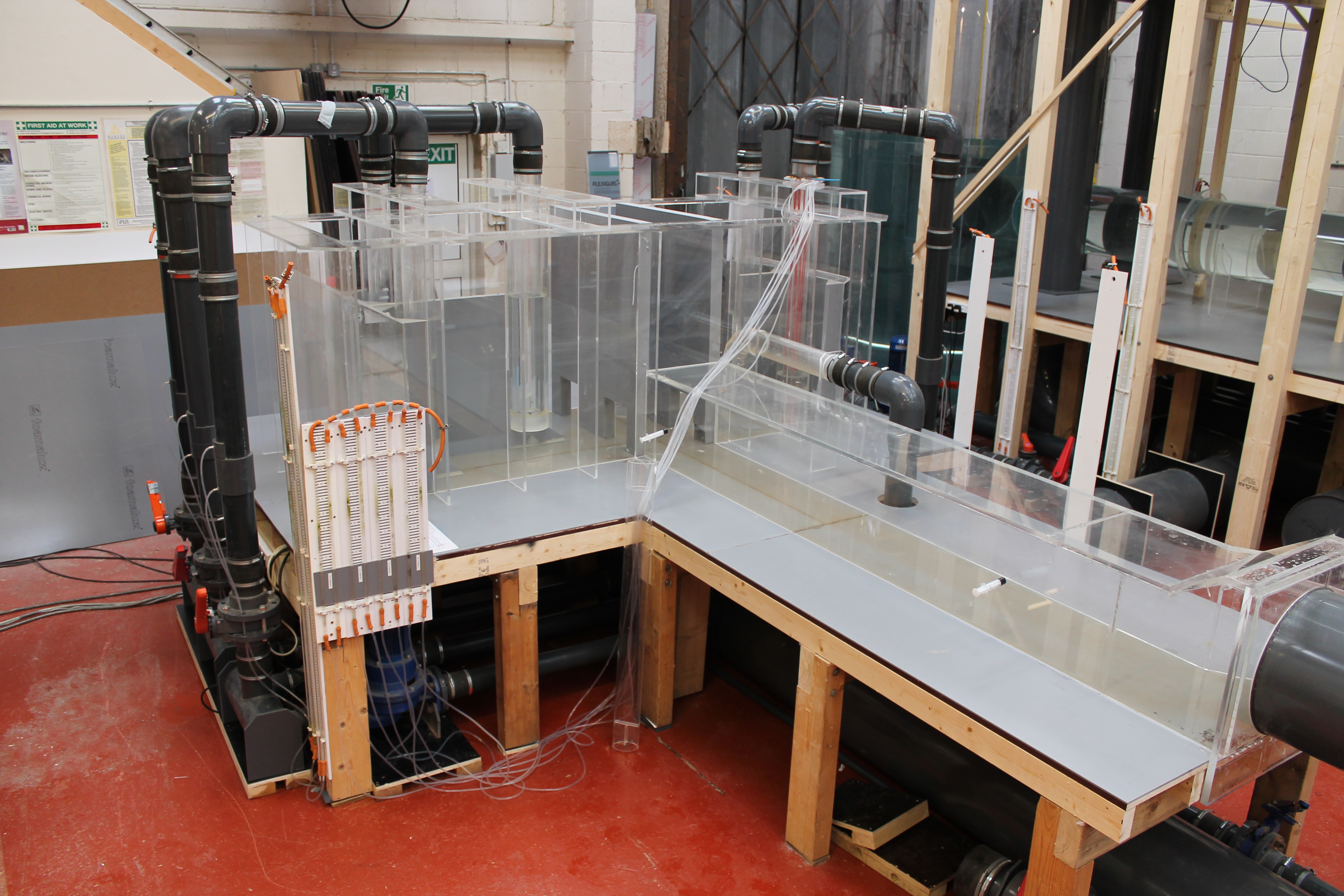
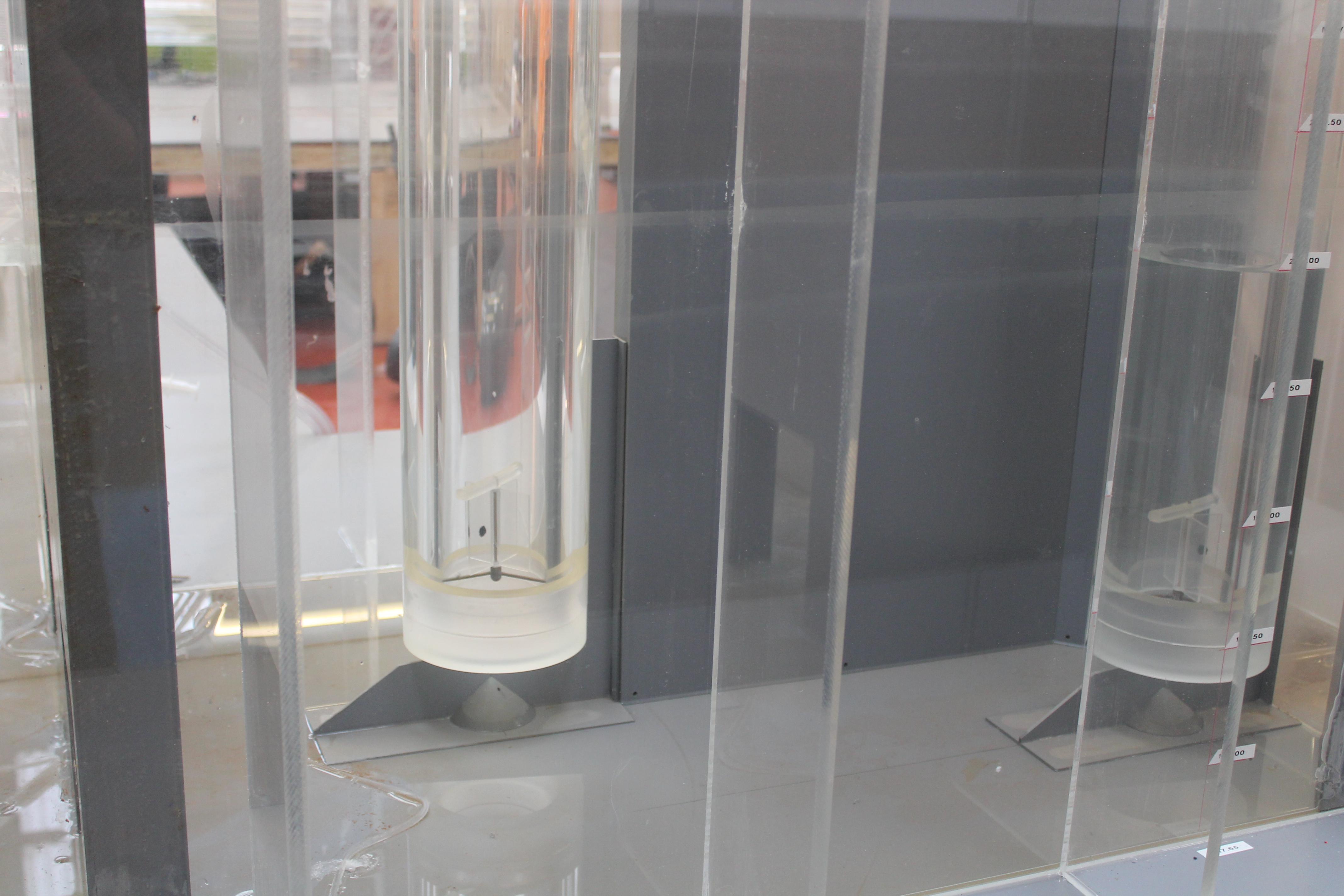
Scale: 1/5th
The station currently is equipped with five propeller submersible pumps, type PL 7061, which are installed within the two suction wells, from the intermediate floor separating the upper discharge chamber and suction wells. The pumps can operate in various combinations with up to a maximum of four running at any one time. Each pump has a rated capacity of 0.84 m3/s.
It was understood that the pumps have exhibited a series of serious failures, including fatigue failure of propeller blade fixings, cavitation erosion of the blades, and resulting bearing and mechanical seal failures.
It was further understood that the hydraulic connection between the central distribution chamber and each of the two lateral wet wells is achieved via two submersible opening pots located at the floor level.
The purpose of the model test was to establish the operating characteristics of the system and to develop the design, where considered necessary, to achieve a satisfactory hydraulic environment over the full range of inflows, screen and pump combinations and water levels. The pumps must operate in an environment where:-
Flow presentation to the pump intakes is acceptable.
No entrained air is drawn into the pump intakes.
Free surface and submerged vorticity are absent.
Pre-swirl rotation is within acceptable limits.
Velocity distribution at the pump impeller is within specified limits
The station exhibits acceptable self-cleansing characteristics.
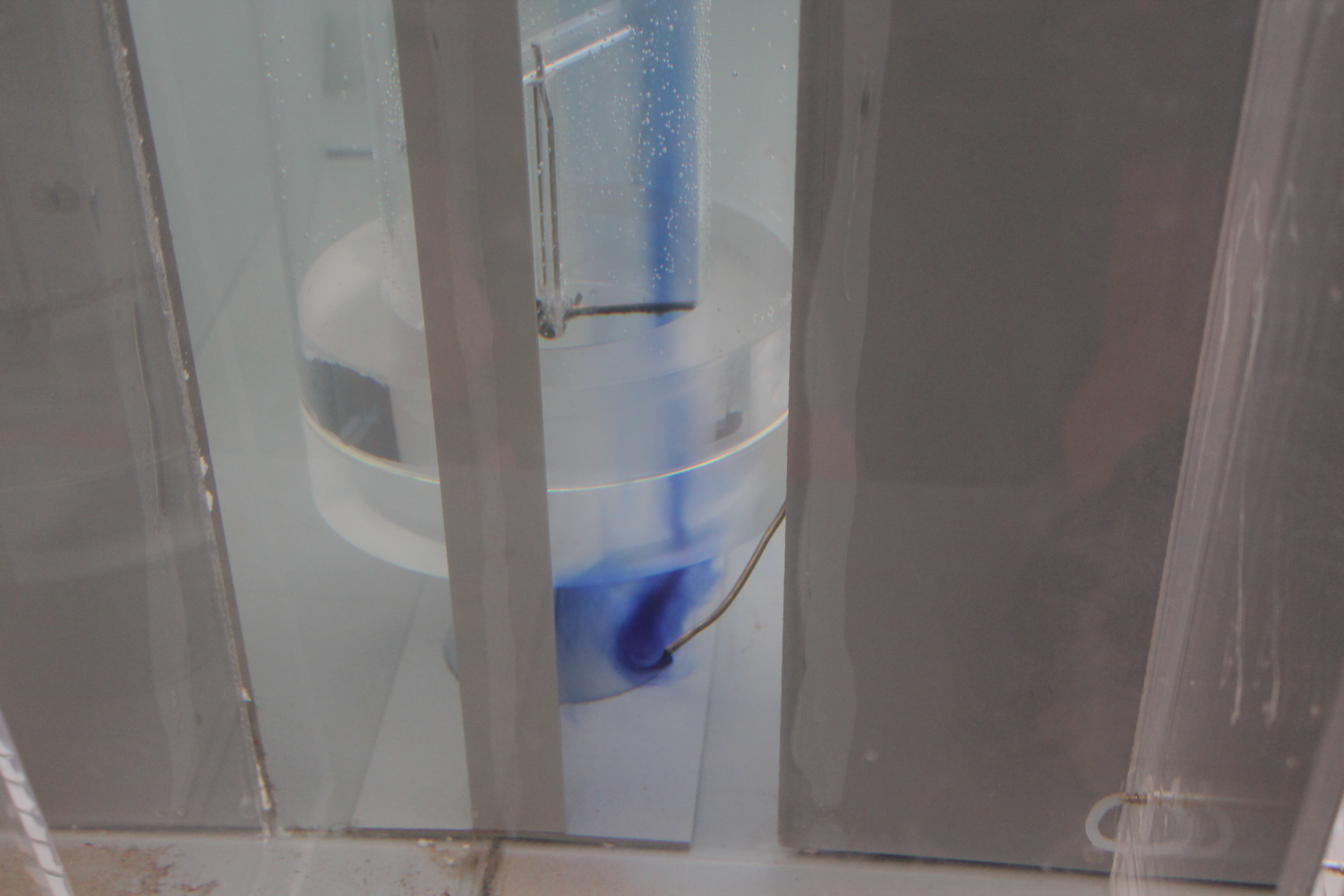
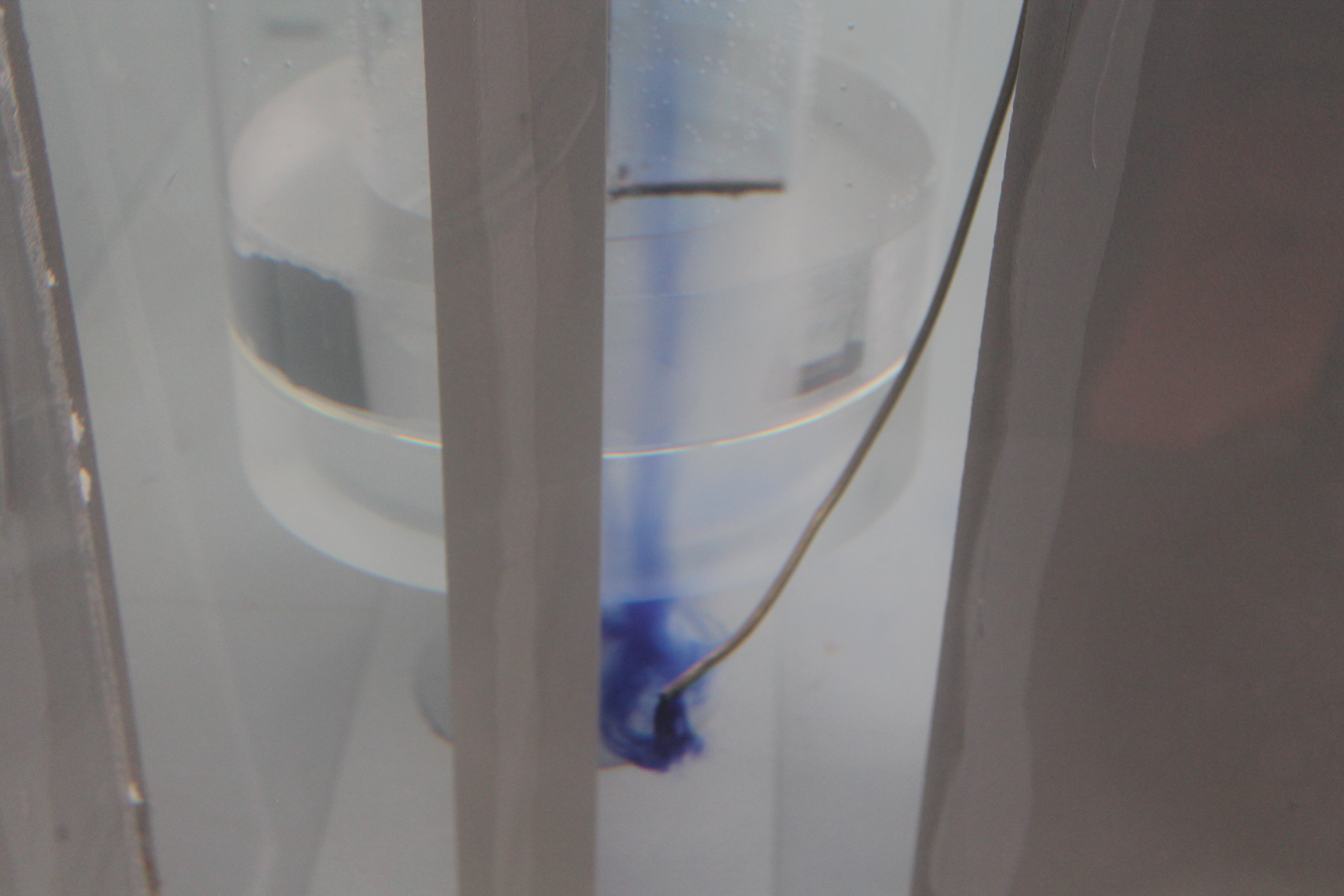
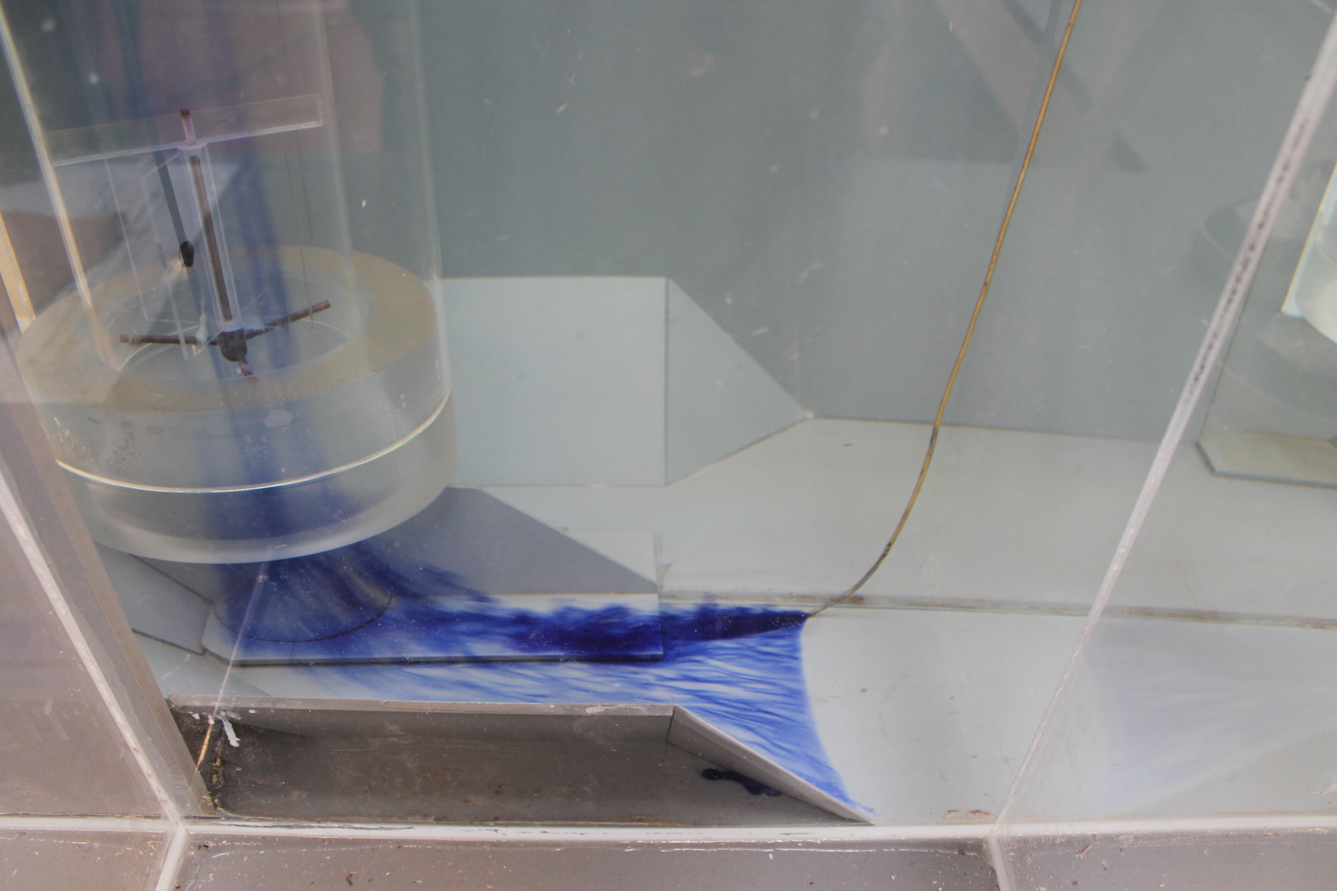
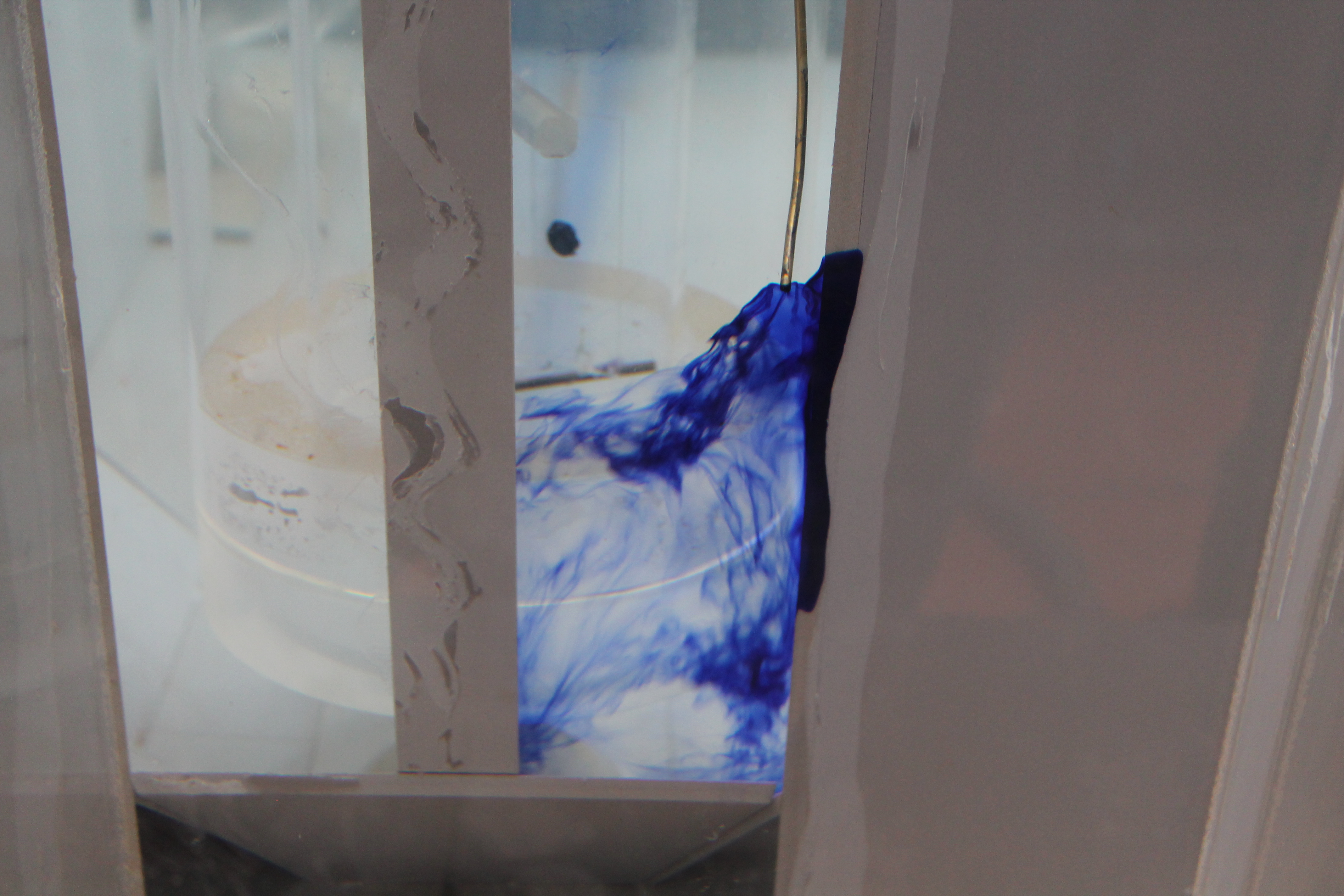
The initial testing programme identified significant areas of non-compliance within the Grimonpont RAS pumping station. All pump units, regardless of combination or water level experienced stable and coherent type 2 submerged vorticity, oblique flow entry and significant turbulence local to the intakes. The four low level ports located within the distribution area, created significant jetting of flow on entry to the wet wells. A less than even distribution of flow was observed between the two openings on each of the dividing walls, as such, a significant bias was evident on the upstream entry port i.e. closest to the inlet channel.
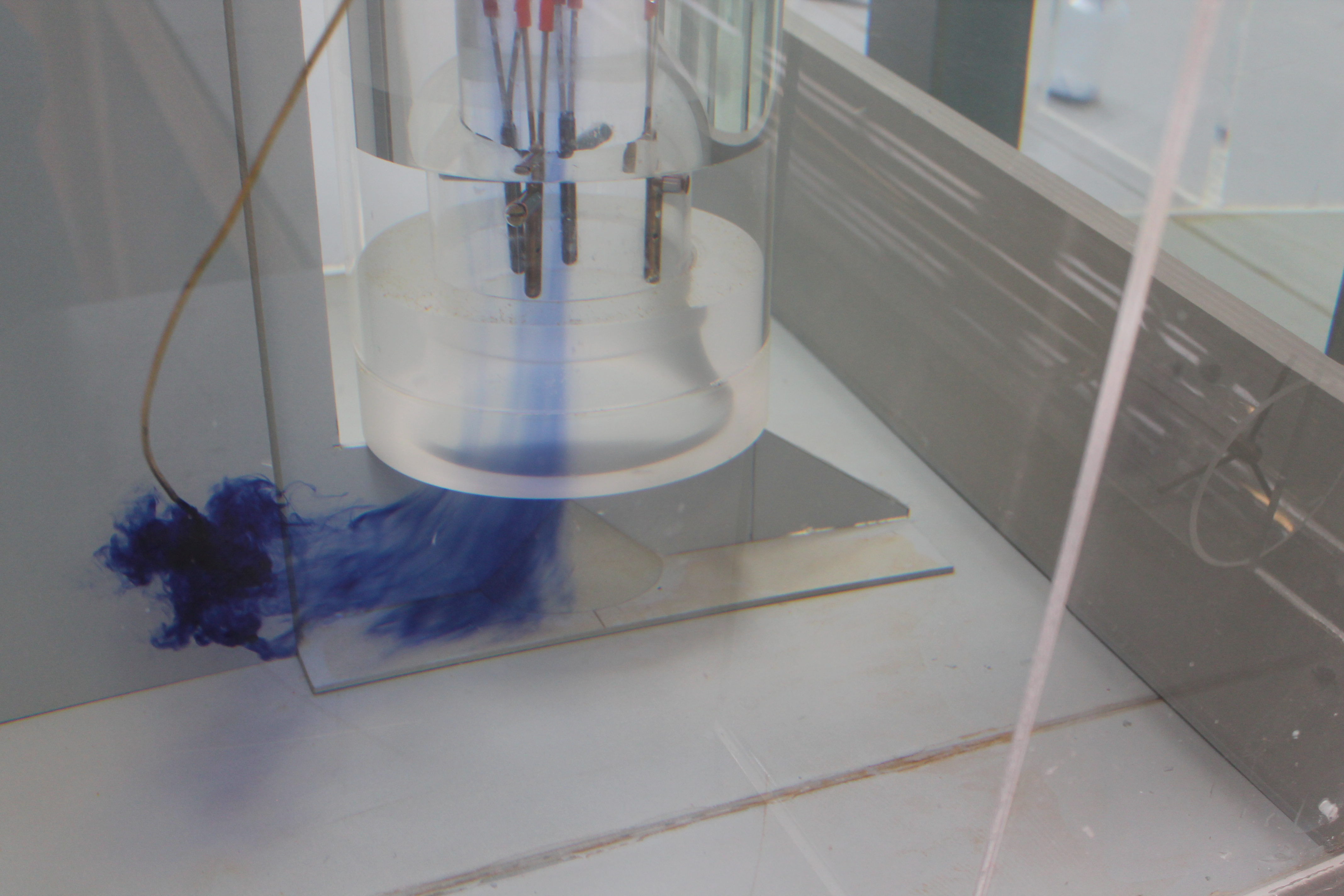
Flow on entry was characterised by a significant high velocity jet, this was more prominent on the upstream ports due to the roll over and complex flow regime produced within the distribution area. The noted high velocity jet was more detrimental within wet well one, due to the location and positioning of pump unit P3, consequently significant asymmetry of flow local to the intake was evident. Observations indicated the high velocity jet created strong passing flow local to the suction, the draw from the pump was insufficient with subsequent flow not altering from the forward trajectory towards pump units P1 and P2.
In addition, bulk flow recirculation was observed within both wet wells, the intensity and associated turbulence was determined by duty pump commination, however, the primary flow paths remained unchanged regardless.
Further to the identification of sub-surface vorticity, the pump units operated in a highly unstable environment with significant asymmetry in the velocity distribution at the suction intakes. This was more prominent local to pump unit P3, we would attribute this to the position and location of the pump unit within the station. Asymmetry and instability in the velocity distribution on the pump suction perimeter may result in significant out of balance radial forces.
These forces may also result in pronounced pump vibration, increased shaft loadings and deflections and, subsequently, reduced bearing and mechanical seal lifetimes. This is particularly pertinent to propeller pumps, such as the Grimonpont pumping station pump units, where asymmetry and vibration effects may be amplified along the vertical drive shaft.
Three pitot scans were undertaken in the current model arrangement with investigation at the maximum one pump out flow of 0.840 m3/s.
A limit of (+/-) 5% variation from the average velocity at the plane of the pump impeller is generally considered as acceptable by the ANSI standard. The recorded values were in the main not within the specified +/- 5% of the mean velocity recognised by the ANSI standard. Operation under such scenarios resulted in bulk deviations in the region of plus 5.2% and minus 12.23%) respectively, these recorded values were identified as been the highest in terms of deviation of the mean velocity, the values were well outside the specified acceptable tolerance of +/- 5% and provided further evidence of the unacceptable operating environment for the pump units.
Peak time averaged (60 second model) values of pre-swirl rotation were measured at the NWL 20.82m. The peak measured values ranged between 4.9 degrees and 1.4 degrees, with the direction of rotation being co-rotational 4.9 and contra-rotational for 4.2. The direction of rotation could be attributed to the primary flow patterns noted throughout initial testing.
The peak values of pre-swirl rotation were generally in accordance with the ANSI Standards (being below 5.0 degrees) and hence, within acceptable limits. However, the characteristic movement of the swirl meter vanes was not indicative of acceptable pump intake conditions. Generally, the swirl meter vanes demonstrated either relatively intense bi-directional movement, which is indicative of unstable flow passing the pump impeller, or coherent uni-directional movement.
Following review of the existing arrangement, several options were required to correct the adverse flows within the vicinity of the five pump intakes. The suggested modifications are sympathetic to site constraints i.e. access to wet well via an 800mm x800mm opening. However, some modifications are above this critical dimension and therefore we would suggest that these modifications are split into manageable sections and retro-fitted within the wet wells. No structural changes or re-location of the pumps is proposed. We would consider the following proposals to optimise the existing arrangement:-
- Opening the ports within the walls of the central distribution chamber- Previous testing determined that the existing low level ports were accelerating flow into the individual wet wells with production of an unsteady and highly turbulent operating environment. By increasing the port aperture to soffit level of the inlet channel, considerably more operating volume was created. Thus reducing velocities and turbulence within the wet wells. Progressive expansion in port volume was investigated until optimisation and confirmation of improvement was gained.
- Bed tripper across the full width of wet well one- Pump unit P3 was subject to high velocity jetting, the introduction of the 800mm high flow tripper directed the inflow to the surface of the wet well thus protecting the pump unit from excessive jetting.
- Cross baffles in each wet well - The cross baffle is located upstream of the pump units within each of the four pump cells. As such, this option would only have a positive influence of pump units P1, P2, P4 & P5. The introduction of the baffles directed flow quiescently towards the pumps with a reduction in surface re-circulation. The baffles act as a quasi-draft tube and as such, the approach velocities can be controlled on approach flow that is both steady, uniform and radial at the suction position. While the length of the baffle is significantly larger than the required 800mm x 800mm it was considered that this could be fabricated in sections and retro-fitted within the wet wells.
- Profiled benching around the suctions- A re-assessment of the sloping infill benching located at the base elevation, around the pump intakes is a critical area of improvement. Testing identified that an excessive open area to the sides of the pumps, located within the cells. It is suggested that the introduction of 45-degree infill benching part way down the cells to aid in streamlining the flow and provide a smoother transition into the pump suction intakes. Implementing this type of benching eliminated side/rear wall vorticity as identified on the model within the previous testing section.
- Flow tripper set at the midpoint within the distribution area- The introduction of a flow tripper on the invert of the distribution area at midpoint suppressed the tendency for flow to enter the wet wells obliquely. Flow will interact with the tripper with roll over and re-direction centrally.
- Re-assessment of the control philosophy- The suitability of level range is discussed within the following section. Optimisation of the level range ensured the station operates under a normal process within an acceptable environment i.e. no adverse hydraulic features.
With the adopted modifications installed, a satisfactory pump operating environment was achieved. Acceptable pump intake conditions were maintained throughout the operating range and pump combinations. The pumps suction operated in an environment free from submerged and free surface vorticity with pre-swirl rotation maintained well within acceptable limits. At no stage was air entrained to the pump suctions on the proviso that the operating levels defined from testing are adhered to.
It is critical that the identified stop levels are adhered to ensure the pumps operate in an environment free from adverse hydraulic effects. The stipulated levels are set prior to the formation of such phenomena and are considered the safe limits of level reduction.
It was understood that pump operation and level range is vital to maintaining site acceptability. As such, a quiescent downstream water level is critical to accurately define the water level within the station. Throughout the initial testing programme, an observed turbulent water surface was evident throughout the station. This was considered detrimental to an accurate level reading, and positioning of the level sensor is critical to achieving an acceptable operating environment.
Moorfield Estate
Yeadon
Leeds LS19 7YA
e: info@hydrotecltd.co.uk
w: hydrotecltd.co.uk

