


- SOUTH JEDDAH - AL KHUMRA SCREEN CHAMBER AND PUMPING STATION
- BRA 3494 – Sabesp Sao Lourenco, High Pressure Pumping Station
- FRANKLEY DE-ALK TRANSFER PUMPING STATION
- Deephams FTFT Pumping Station and Inlet Culvert
- Riverside Sewage Treatment Works - Regional Sump 1
- La Villette Pumping Station
- Bewsey Bridge Pumping Station
- Suez Thermal Power Station - Intake Pumping Station
- Norway Road Pumping Station
- Grimonpont RAS Pumping Station
- Nab's Head Storm Inlet Channel and Storm Pumping Station
Pumping Stations
SOUTH JEDDAH - AL KHUMRA SCREEN CHAMBER AND PUMPING STATION
Client: ABULIJADAYEL CO. CONTRACTING & MAINTENANCE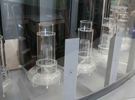
Scale: 1/8th
The South Jeddah – Al Khumra Lift Pumping Station comprised of a screen chamber, pump sump and discharge chamber. The Pumping Station was designed to accommodate an inflow range between 0.50m3/s and 14.50m3/s. Flow was delivered to the screen chamber via a 3.0 diameter inlet pipe which discharged flow into the screen forebay. Flow from the forebay fed six screen channels which in turn discharged into a confluence chamber. As the screen chamber was constructed in a separate caisson upstream of the Pumping Station, twin 3.0m diameter connecting tunnels conveyed flow from the confluence to the inlet chamber of the Pumping Station.
The Pumping Station included three sumps with each sump containing eight submersible KSB pump units. It is understood that the pumps operated on a seven duty one standby bias with each pump nominally rate 1.0m3/s. It was considered that one pump in each sump will act as a standby unit with the pump duties rotated. Flow was delivered to the Pumping Station inlet chamber via the twin 3.0m diameter connecting tunnels. Each sump included a ported baffle arrangement to aid flow distribution.
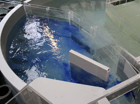
The purpose of the model study was to establish the operating characteristics of the system and to develop the design, where considered necessary, to achieve a satisfactory hydraulic environment over the full range of inflows, screen and pump combinations and water levels. The screens and pumps must operate in an environment where:-
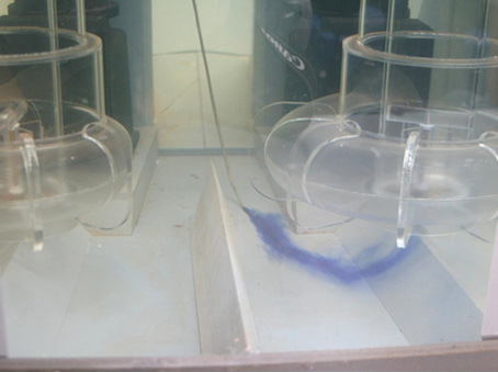
- Flow presentation to the screens is acceptable.
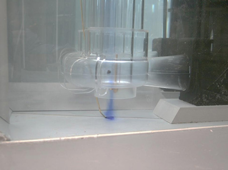
- Flow presentation to the pump intakes is acceptable.
- No entrained air is drawn into the pump intakes.
- Free surface and submerged vorticity are absent.
- Pre-swirl rotation is within acceptable limits.
- The screens and pump sumps remain materially self-cleansing
In respect of the Screen Chamber, the Institute of Water Pollution Control (IWPC) publication ‘Manual of British Practice in Water Pollution Control – Preliminary Processes’ was adopted to provide the minimum standards for this model study with application and reference to the following areas:-
- Flow regime: The screen channels should provide an even velocity distribution, free from excessive turbulence. The channels should be smooth and regular and avoid leading edges that may potentially collect screenings and low velocity areas that may collect grit.
- Velocity: A minimum velocity of 0.5 m/s is advised to prevent the accumulation of grits within the screen channels. A maximum velocity of 1.0 m/s (refer to manufactures detailed requirements), is usually recommended to prevent screenings scour and potential punch through. Velocities up to 1.50 m/s can be tolerated if not persistent.
Moorfield Estate
Yeadon
Leeds LS19 7YA
e: info@hydrotecltd.co.uk
w: hydrotecltd.co.uk

