


- SOUTH JEDDAH - AL KHUMRA SCREEN CHAMBER AND PUMPING STATION
- BRA 3494 – Sabesp Sao Lourenco, High Pressure Pumping Station
- FRANKLEY DE-ALK TRANSFER PUMPING STATION
- Deephams FTFT Pumping Station and Inlet Culvert
- Riverside Sewage Treatment Works - Regional Sump 1
- La Villette Pumping Station
- Bewsey Bridge Pumping Station
- Suez Thermal Power Station - Intake Pumping Station
- Norway Road Pumping Station
- Grimonpont RAS Pumping Station
- Nab's Head Storm Inlet Channel and Storm Pumping Station
Pumping Stations
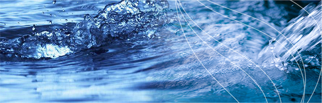
Riverside Sewage Treatment Works - Regional Sump 1
Client: INTERSERVE CONSTRUCTION LTD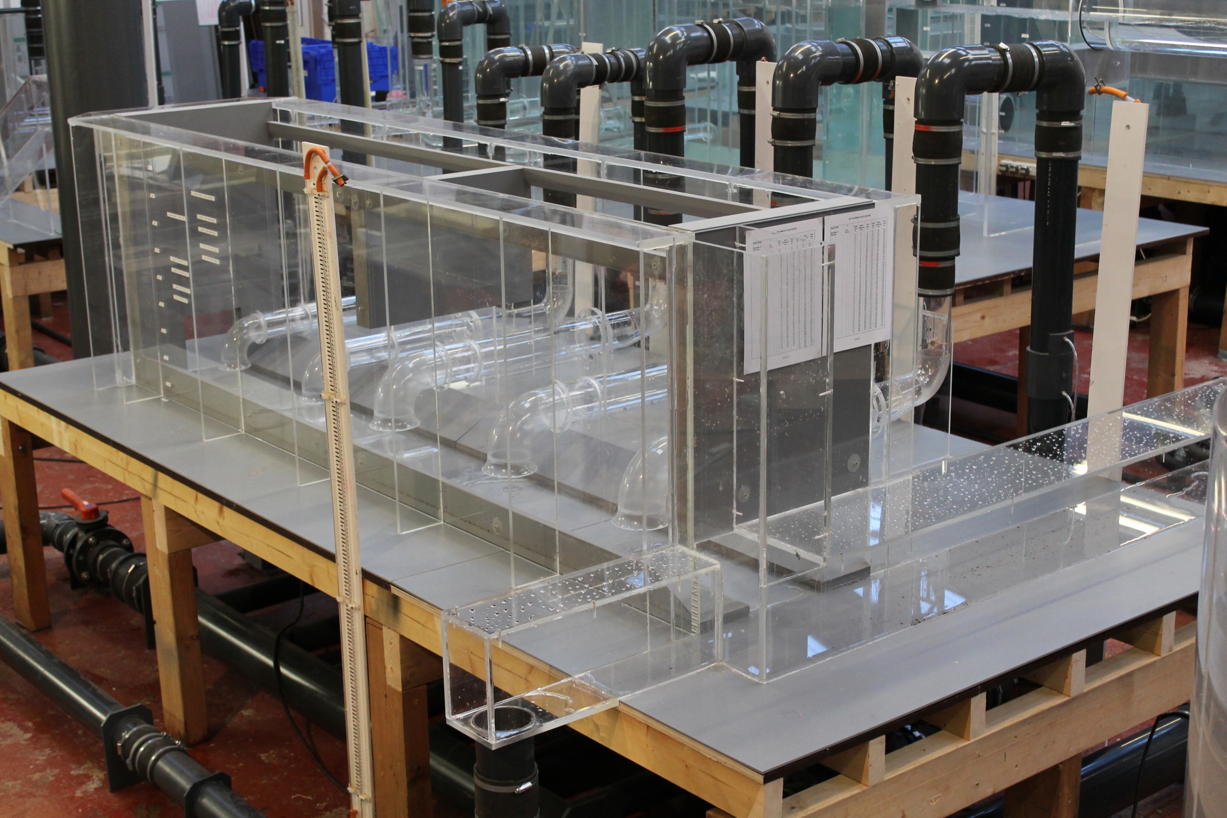
Scale: 1-6
Initial testing
The initial testing programme identified significant areas of non-compliance within the sump throughout the inflow and level range. It was considered that the problems identified on site i.e., vibration, cavitation and increase in mechanical wear were attributed to the adverse hydraulic phenomena’s noted throughout this phase of testing.
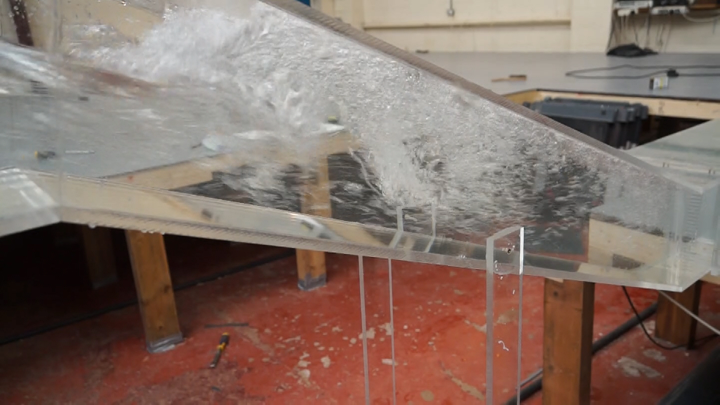
Testing confirmed that significant air ingestion to pump units R1 and R2 under high inflow rates was evident. While the water level within the sump reduced, testing determined that the five stages of the progression to a strong hydraulic jump were defined at the invert level change within the inlet culvert. Significant energy dissipation was evident via the supercritical inflow jet; energy was dissipated through the frictional losses and resistance within the channel, resulting in a decrease in velocity and an increase in depth.
This in turn produced a hydraulic jump initially classified as an undular jump, a mild unsteady oscillating wave pattern but in the main forward velocities were achieved. A reduction in water level produced the next phase of a weak but profound jump; the supercritical flow path produced an oscillating jet with a roll over and formation of a mild standing wave with irregular characteristics and formation. A further reduction in water level saw the final phase of development, the high component of velocity jet ingested intermittent slugs of water rolling down the front face of the jump, generating wave patterns downstream with a rough water surface profile evident.
The turbulent energy exchange had created significant air suspension within the downstream flow regime. Flow on transport to the sump was considerably aerated and due to the sealed culvert no air release was observed until sump entry.
The aerated flow released a significant amount of air to the free surface immediately on sump entry; however, observations concluded that due to the high velocities produced by the low level inlet port, significant air ingestion was experienced by pump suctions R1 and R2.
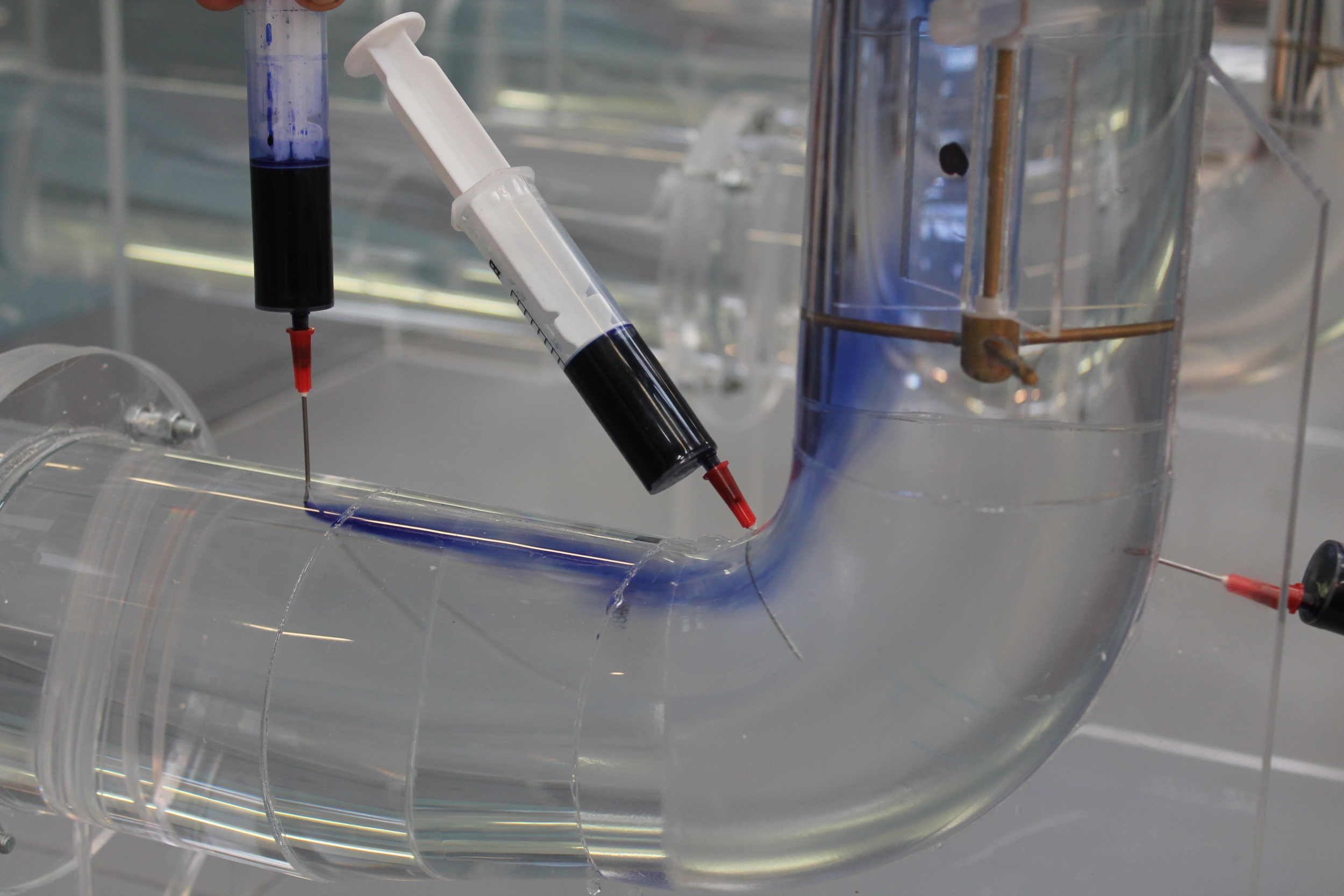
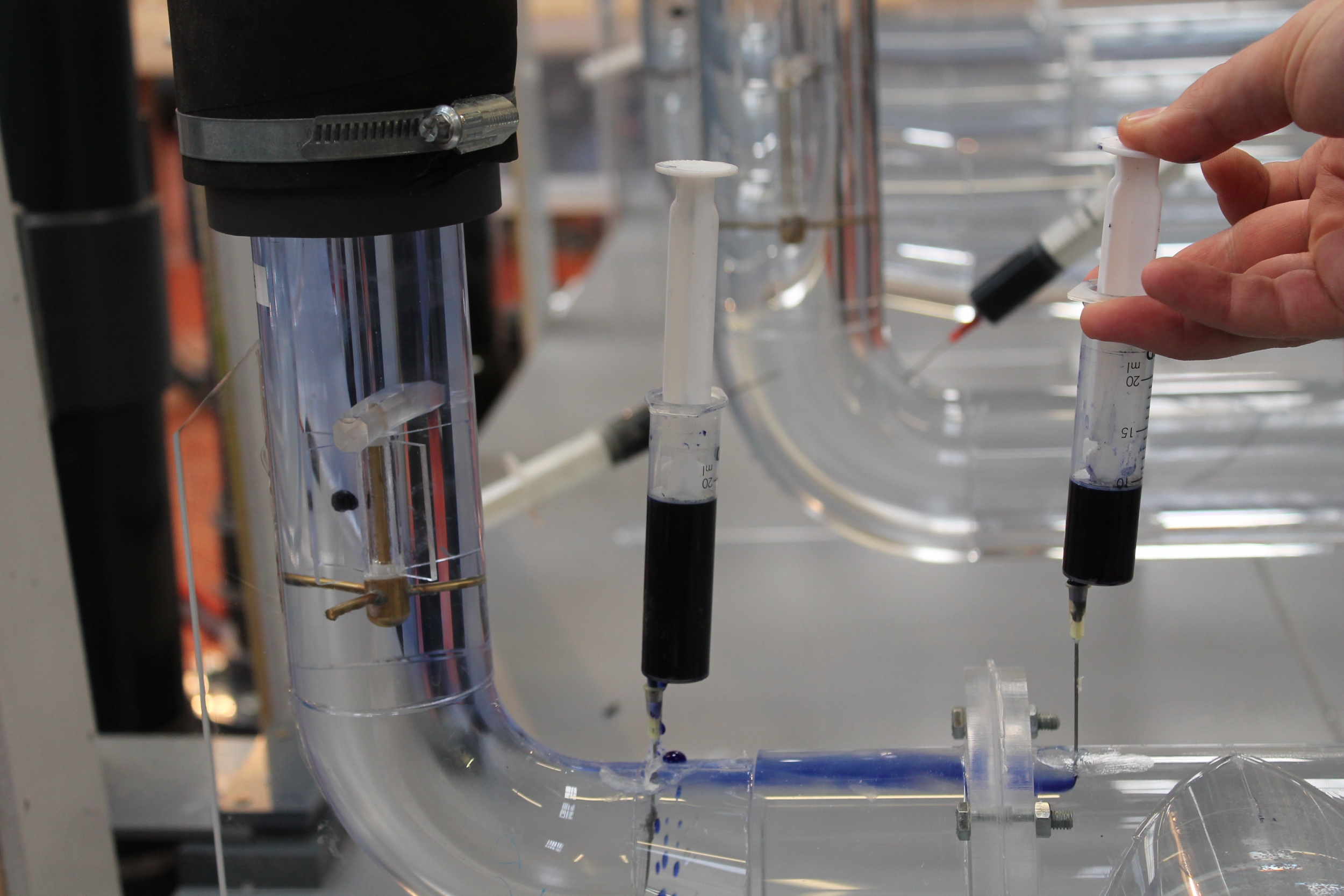
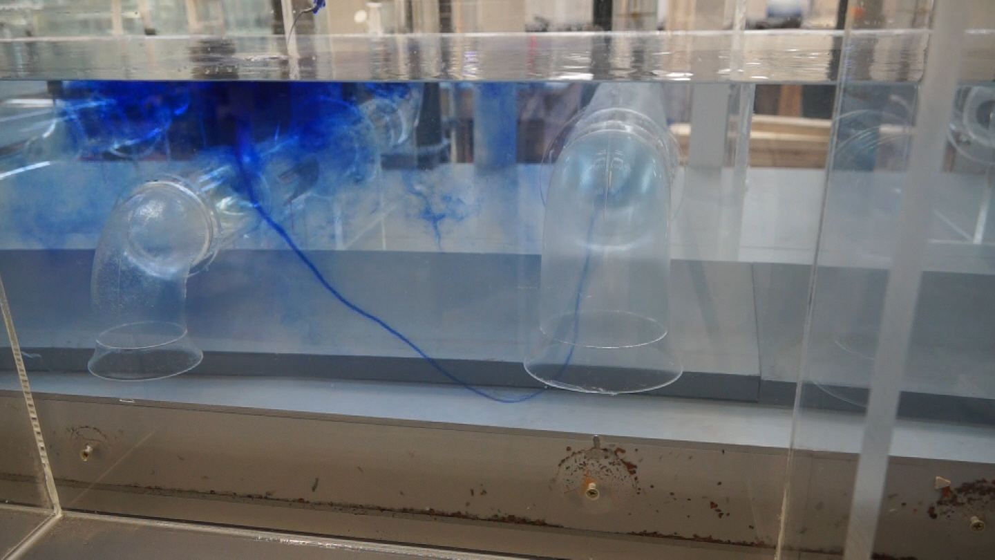
Flow local to the suction intakes was considered unsteady with asymmetry within the velocity distribution evident. Flow entered the sump via the low level port in a high velocity jet; this was further qualified by the fluttering nature of the swirl meter vanes. In addition, the initial testing programme identified persistent submerged vorticity classified as Type 2, with progression to Type 3 on units R1 and R2 at the duty stop level. This type of vorticity can have a significant effect of the performance of the pump units, testing determined that the intensity of sub-surface vorticity on pump units R1 and R2 increased to an intermittent Type 3, as the intensity of rotation increases, the local static pressure within the vortex core falls to a value where air is drawn out of solution, as noted on the model by a static air core.
High intensity rotation caused the water at the core to vaporise at a pressure fractionally above absolute zero. Under these conditions, high frequency vibration and cavitation erosion can occur, the latter causing rapid damage to the suction pipework. The alternative suctions when assigned duty still experienced a stable and coherent sub-surface vorticity classified as Type 2 in nature which penetrated through the suction bellmouths and into the horizontal section of suction pipework.
In addition, under low water level test case scenarios, all pump suctions when assigned duty experienced Type 6 surface vorticity, this type of vorticity forms on the surface of the water and has enough intensity to pull air from the surface and into the suction pipework, resulting in significant air ingestion. The general flow patterns within the sump were considered the main contributing factor to induce the surface vorticity. The nature of flow re-circulating within the sump and the intense vortex core above the suction bellmouths allowed a stable surface vortex to form which had enough energy from the duty pump to pull a full air core through the water volume and into the pump suction.
Development
Following review of the existing arrangement, numerous options were required to correct the adverse effects evident within the arrangement. The suggested modifications are sympathetic to site constraints i.e. access to the wet well could be difficult. Therefore, some modifications could be split into manageable sections and retro-fitted within the wet well. No structural changes or re-location of the pumps is proposed. We would consider the following proposals to optimise the existing arrangement.
- Horizontal plate and air discharge chimney:-
A horizontal plate located on the soffit within the sealed inlet culvert is required to collect and transport accumulated air created by the turbulent hydraulic jump (standing wave). Air is transported towards the sump on the soffit of the sealed culvert, as such; the introduction of a horizontal plate spanning the full length of the culvert local to the low level inlet port, re-directed the accumulated air into a proposed discharge chimney within the sump. The chimney extends above the TWL level of minus 2.45 mAOD to allow air release to the free surface.
Without the inclusion of the horizontal plate and associated discharge chimney, bulk air ingestion would occur to pump units R1 and R2 whilst operating under a high inflow rate. As discussed previously, this can lead to significant deterioration in pump performance and mechanical wear.
- Flow deflector block:-
A flow deflector block opposing the low level inlet port spanning the full width of the sump located centrally on the invert was required to alter the general flow characteristics and protect pump units R1 and R2 from the observed high velocities and significant cross flow.
Without the inclusion of the flow deflector block, significant cross flow would be experienced local to the pump suctions i.e., R1 and R2, this in turn created asymmetry in the velocity distribution at the suction intake. The associated turbulence was transported through to the pump impeller with unsteady movement of the modelled swirl meter vane.
With alteration to the general flow patterns from within the sump, operation at the duty stop level ensured that the surface vorticity observed on all operative suctions was suppressed and formation of a coherent Type 6 (air entraining), vortex could not develop.
- Suspended baffle above pump unit R4:-
A suspended baffle located above pump unit R4 was required to protect the pump unit from surface vorticity, due to its location within the sump, operation at the duty stop level observed flow short-circuiting above the suction bellmouth. Consequently, formation of a stable and coherent Type 6 (air entraining) vortex was evident. To suppress the flows tendency to rotate into a tight vortex core, the introduction of the suspended baffle at an elevation of minus 4.06 mAOD re-directed the flow vertically towards the invert of sump. As such, the noted surface vorticity did not form and develop into a Type 6 air entraining vortex.
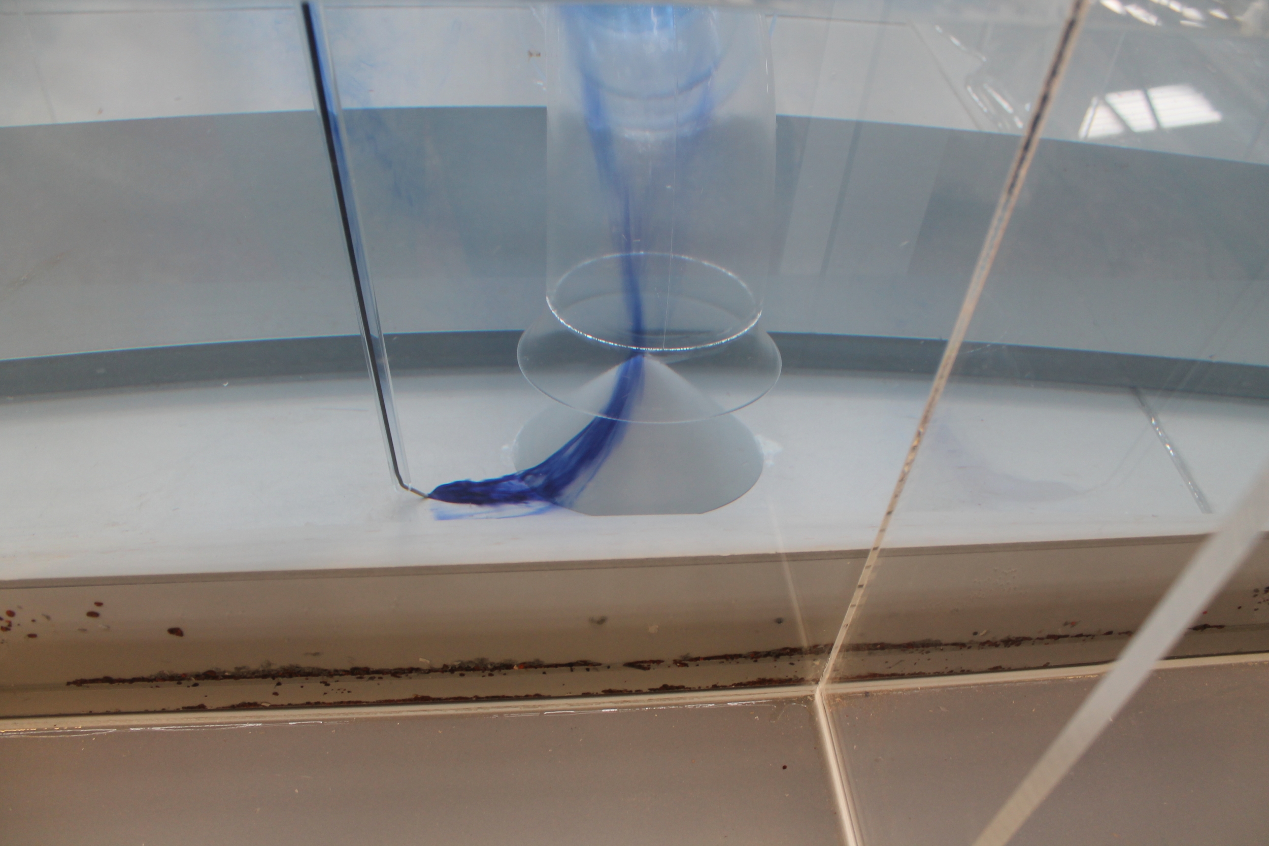
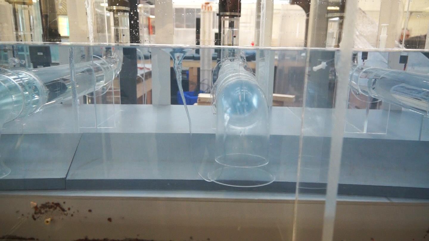
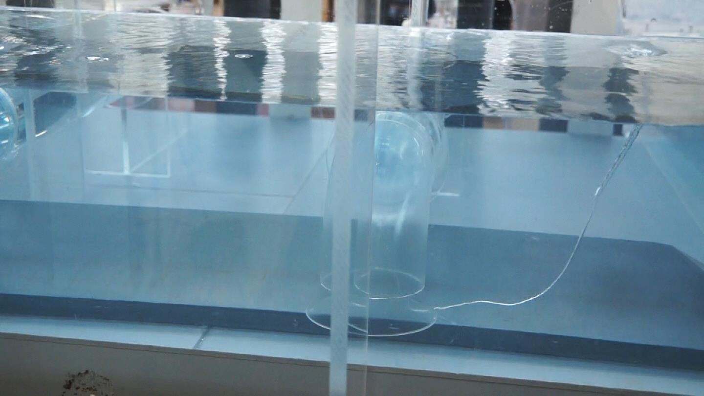
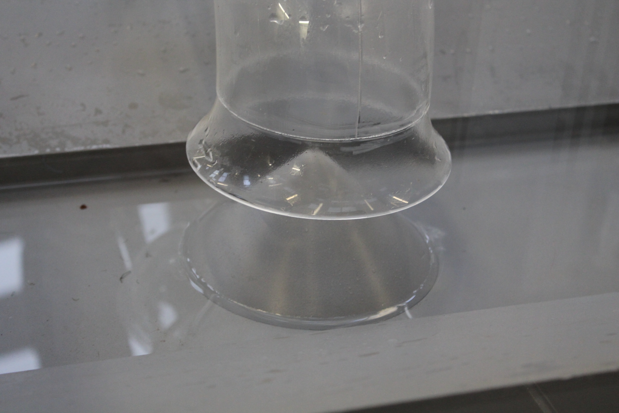
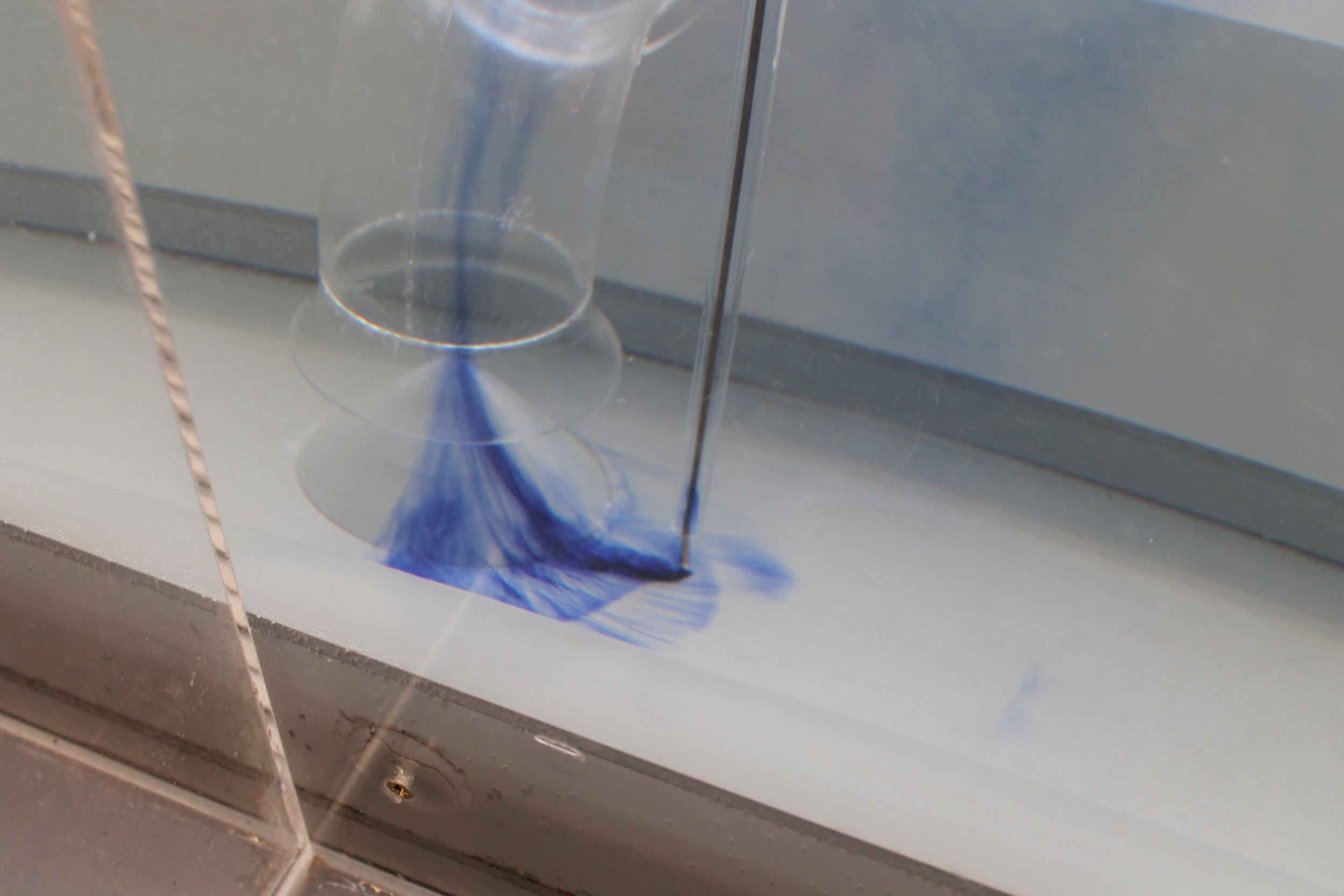
- Suction cone:-
The suction cone is required under all suction intakes to promote a uniform velocity profile on entering the pump suction. The cone installed centrally, supressed the coherent sub-surface vorticity observed throughout the initial assessment. The cone will also deny the vorticity a formation point, thus reducing the phenomena from forming.
Final testing
With the adopted modifications installed, a satisfactory pump operating environment was achieved. Acceptable pump intake conditions were maintained throughout the operating range and pump combinations. The pump suctions operated in an environment free from submerged and free surface vorticity with pre-swirl rotation maintained well within acceptable limits. At no stage was air entrained to the pump suctions on the proviso that the operating levels defined from testing are adhered to.
A review of the suction pipework was undertaken on all alternative arrangements within the sump. Testing confirmed that with the adopted modifications installed, each individual element on all of the alternative suction pipework were free from any adverse hydraulic effects. Mild flow separation was observed at the ninety degree bends on approach to the pumps, however, this is an inevitable feature and would be extremely difficult to correct. It is considered that the observed flow separation would not be detrimental to the pumps and was not the contributing factor to the problematic issues experienced on site.
Moorfield Estate
Yeadon
Leeds LS19 7YA
e: info@hydrotecltd.co.uk
w: hydrotecltd.co.uk

