


- SOUTH JEDDAH - AL KHUMRA SCREEN CHAMBER AND PUMPING STATION
- BRA 3494 – Sabesp Sao Lourenco, High Pressure Pumping Station
- FRANKLEY DE-ALK TRANSFER PUMPING STATION
- Deephams FTFT Pumping Station and Inlet Culvert
- Riverside Sewage Treatment Works - Regional Sump 1
- La Villette Pumping Station
- Bewsey Bridge Pumping Station
- Suez Thermal Power Station - Intake Pumping Station
- Norway Road Pumping Station
- Grimonpont RAS Pumping Station
- Nab's Head Storm Inlet Channel and Storm Pumping Station
Pumping Stations
Bewsey Bridge Pumping Station
Client: MWH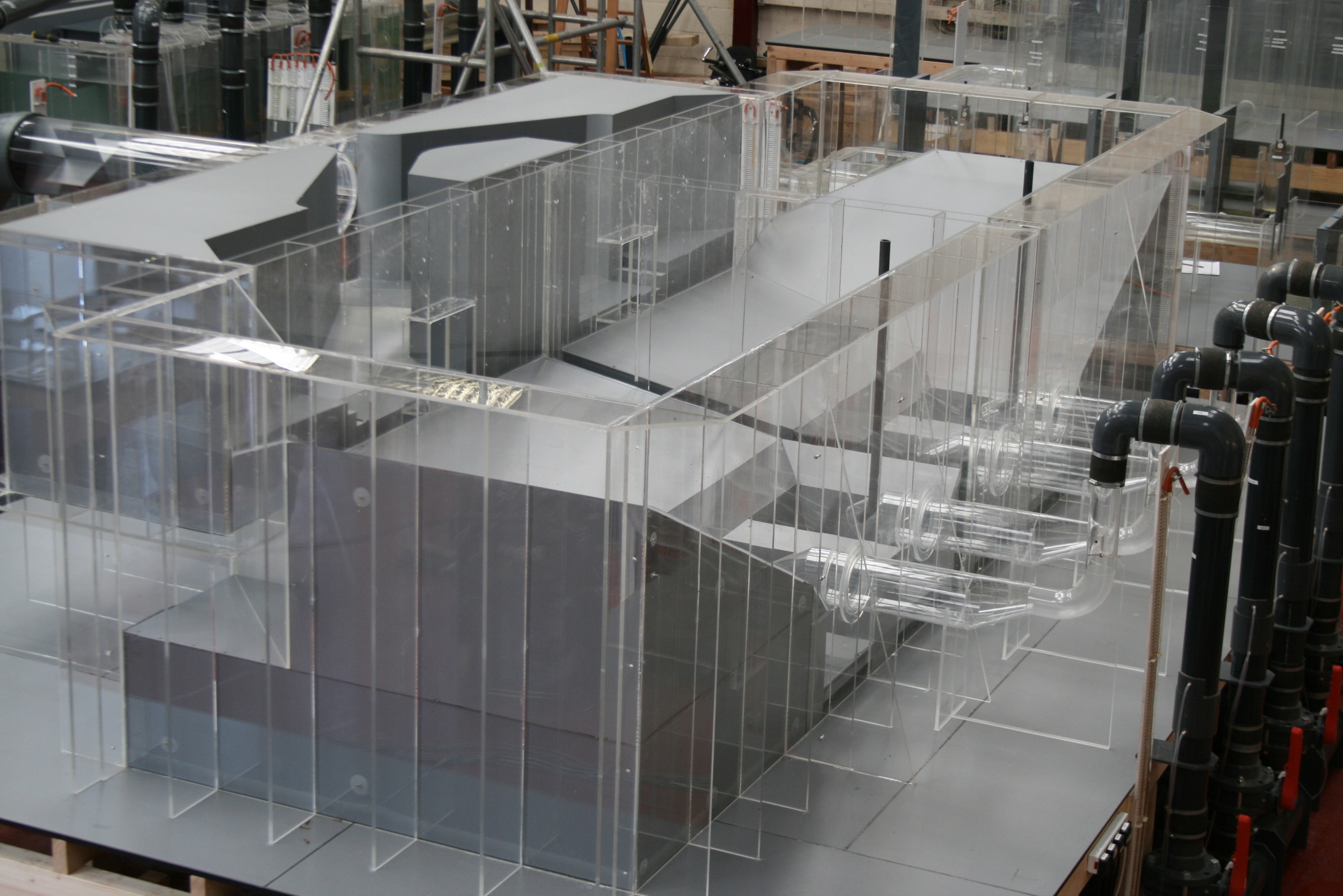
Scale: 1:5
The Bewsey Bridge Pumping Station project is a major capital investment scheme designed to resolve maintenance and other issues on the existing pumping station site in the Warrington area, UK.
Currently, two sewers feed into the Bewsey Bridge site, designated the Sankey Millingford and the Sankey Valley sewers. These two sewers currently discharge into two independent pumping stations, which lift the full flow into a combined 1200 mm diameter steel rising main, which transfers flow to Gatewarth WwTW. A combined sewer overflow (CSO) on site receives the full flow from the Sankey Valley sewer and surplus flows from the Sankey Millingford sewer. Various cross connections and weir arrangements on site allow flow to divert between the two pumping stations.
The purpose of the scheme was to rationalise the on-site pipework by diverting the full flow from the Sankey Millingford sewer through the CSO, by minor modifications to the weir arrangements within existing chambers, and from there divert the full flow into a new pumping station that will replace the two existing stations, which both suffer from operational and maintenance issues.
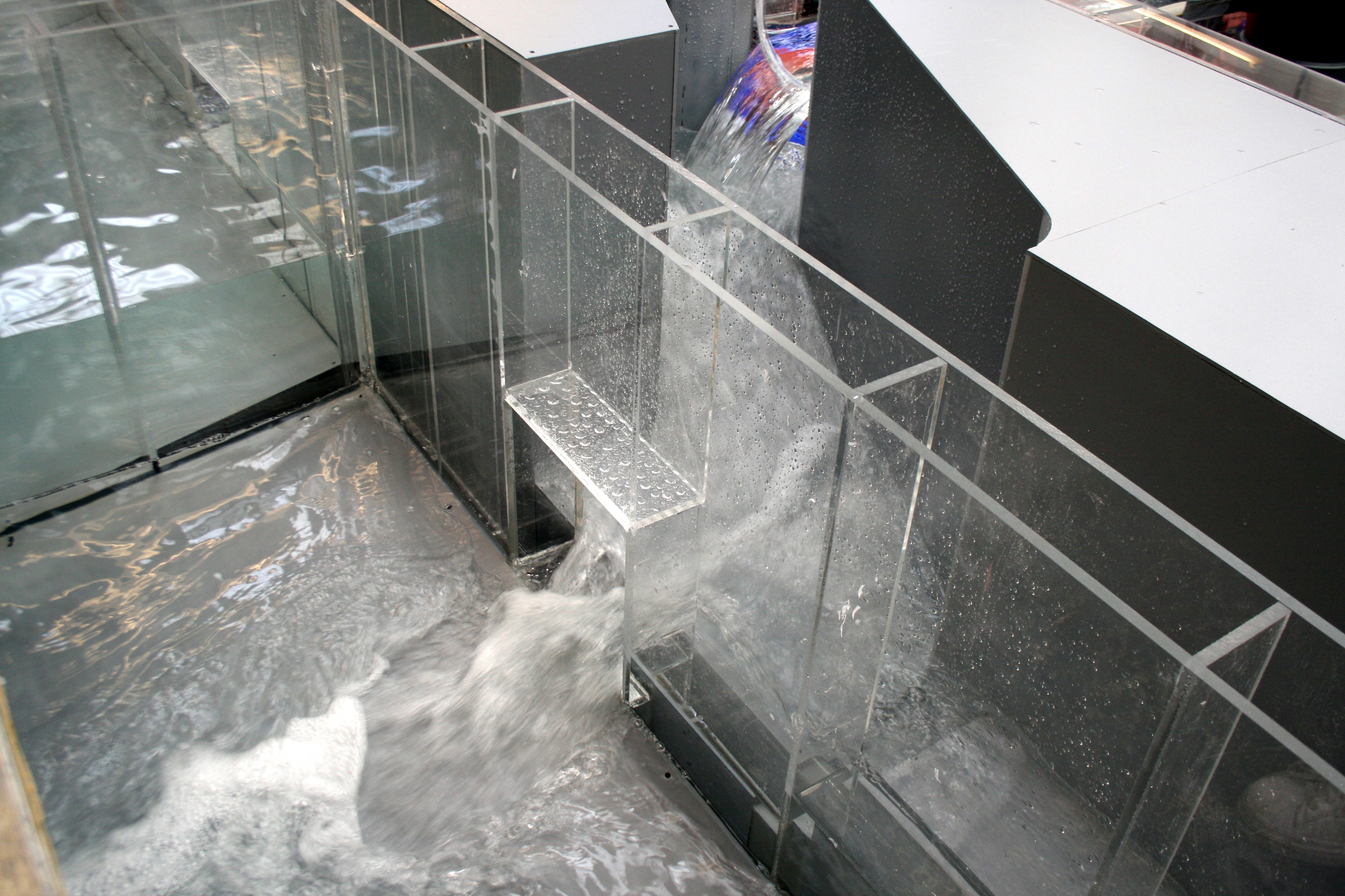
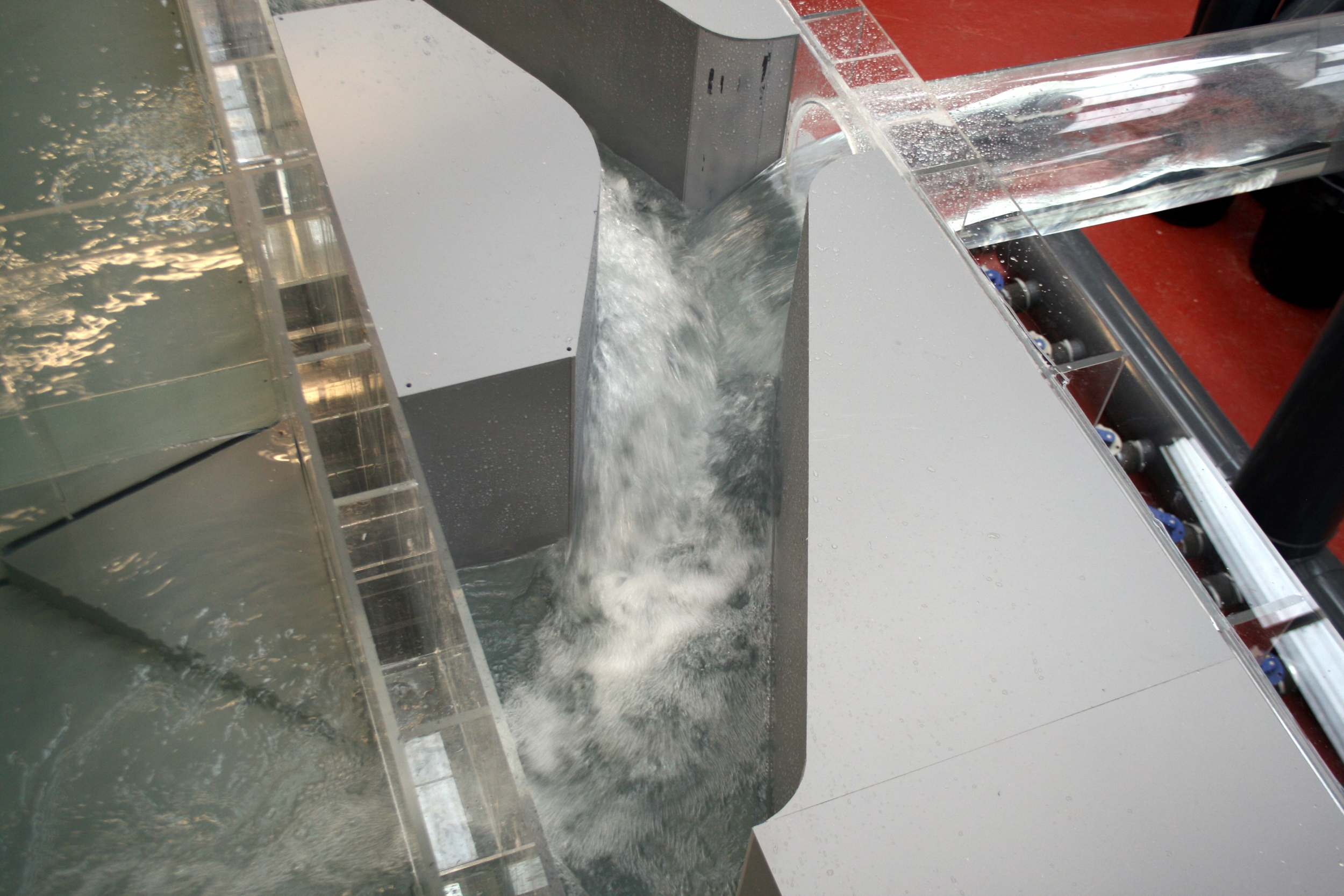
The two incoming sewers combined will gravitate between 180 l/s and 4421 l/s to be roughly split equally between the two with the Sankey Millingford sewer delivering fractionally more to the site. Of this inflow, the proposed new pumping station will pass forward a maximum flow of 1890 l/s, with any additional flow to spill to storm over a screened CSO.
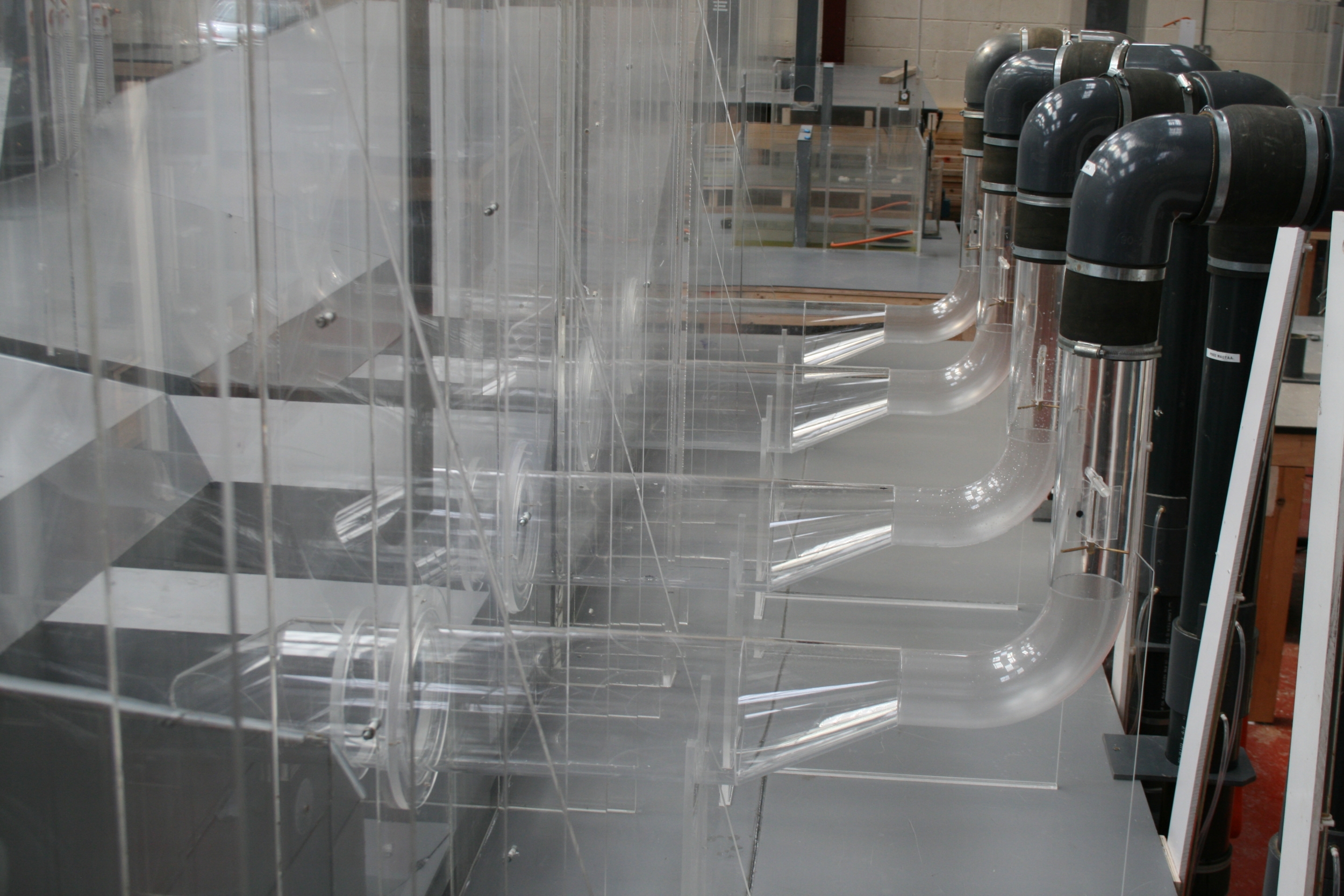
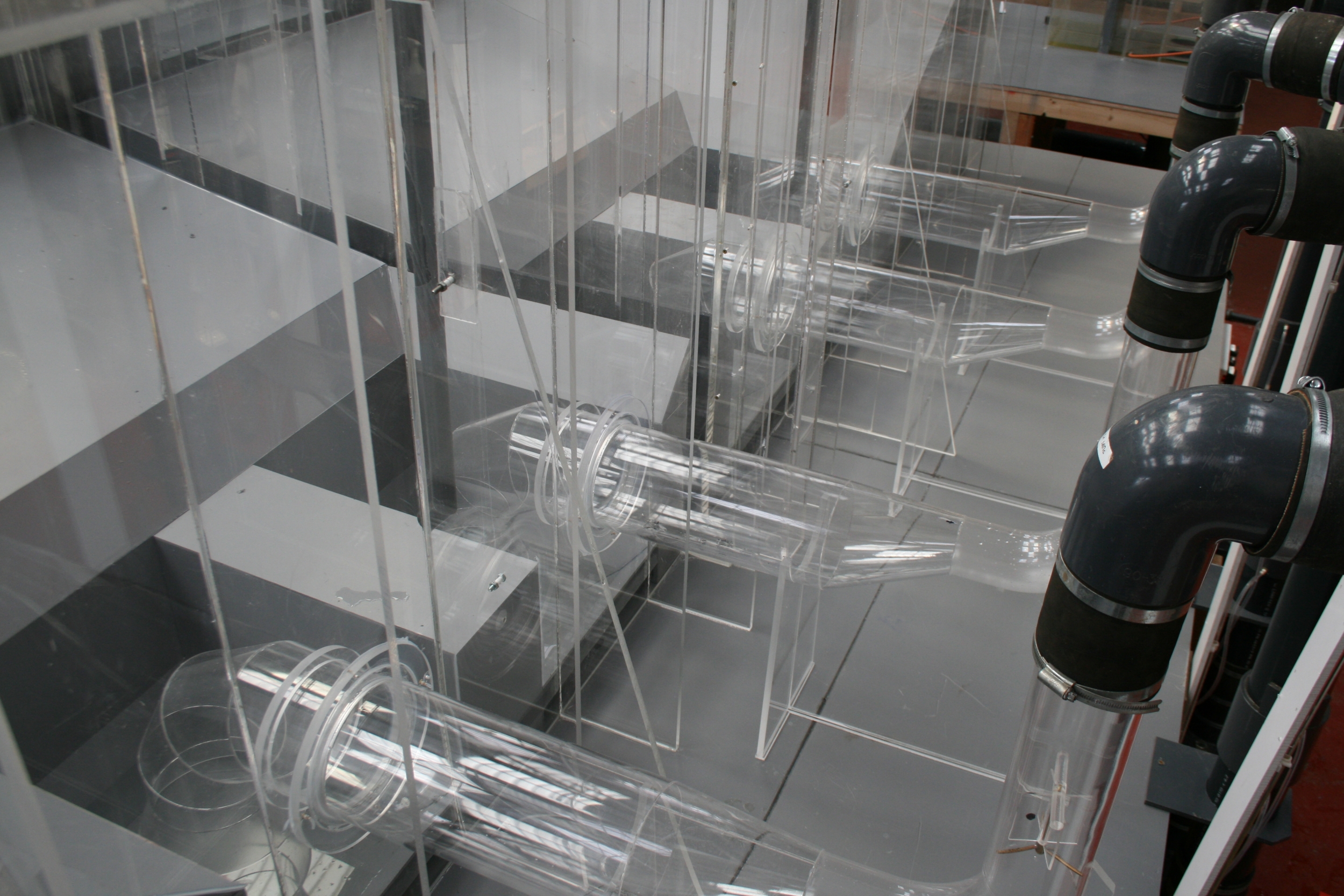
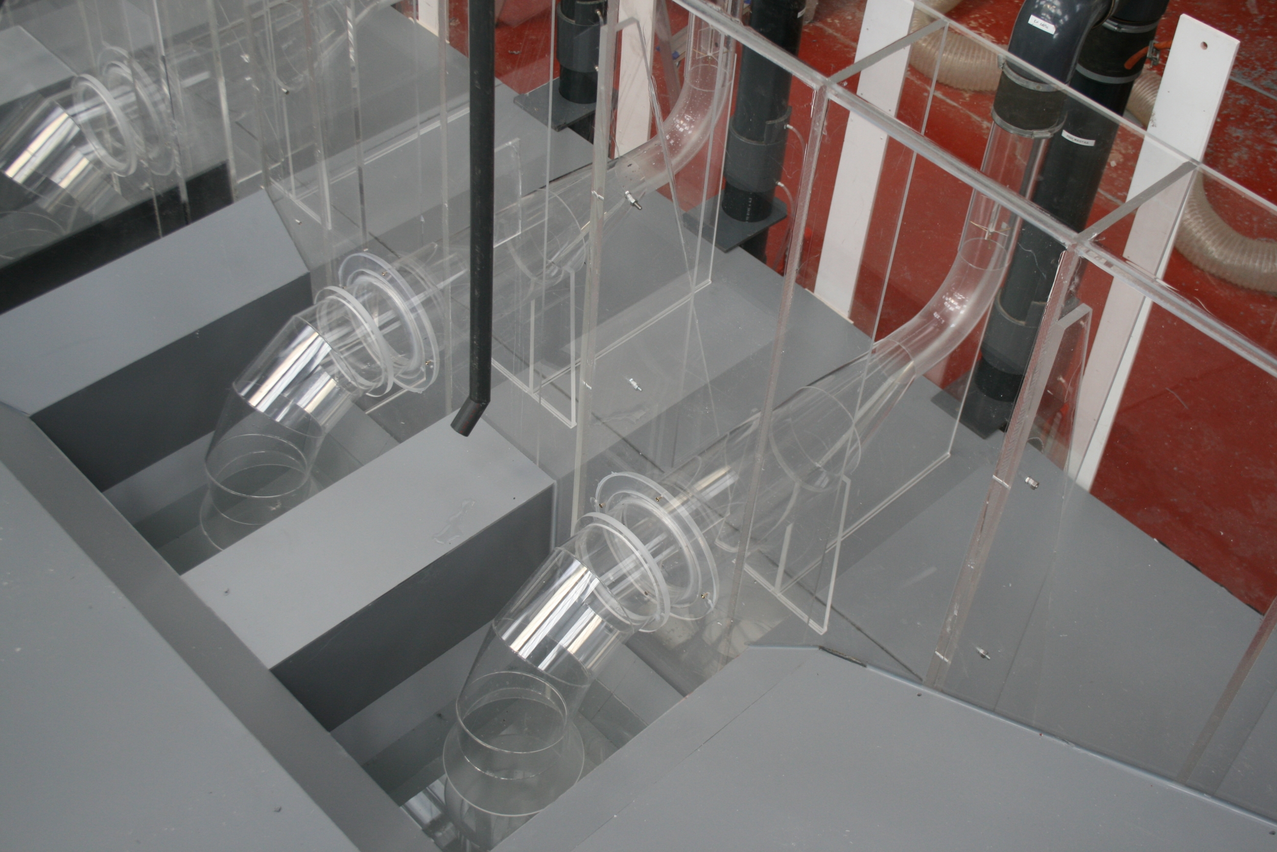
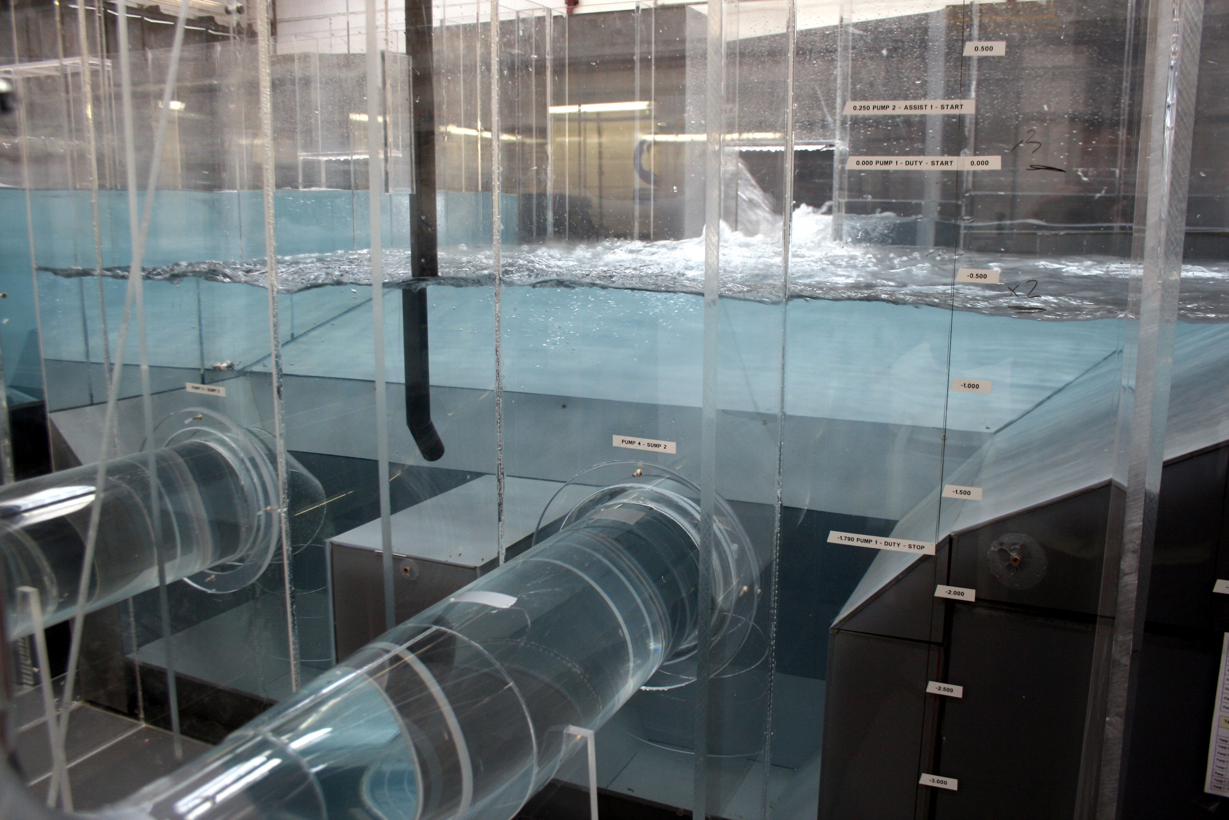
Flow entering the pumping station will immediately pass into a distribution chamber, where, under normal operation, flow will bifurcate equally before being delivered into two similar wet wells. The two similar (but handed) wet wells are essentially rectangular with a maximum footprint of 12.20 m x 7.90 m and, are each equipped with a low level sump. Each wet well will be equipped with two similar 1046 mm diameter suction with 800 mm diameter suction pipework, reducing down to 400 mm diameter via an eccentric taper, located immediately downstream of a dedicated isolation valve and upstream of a short radius 90-degree bend. The four KSB Sewatec dry well mounted, variable speed pump units, will deliver individual flows of between 300 l/s and 630 l/s to a common 1200 mm diameter rising main, which will deliver the combined flow from the pumping station to Gatewarth WwTW.
Under normal operation both sumps will operate simultaneously with the pumps running on a D/A/A/S basis to deliver between 300 l/s and the peak outflow of 1890 l/s. As there is no direct interconnection between the two sumps, they may, depending on the discharge rate, operate at different levels during free discharge periods, as the outflow from the sumps will vary.
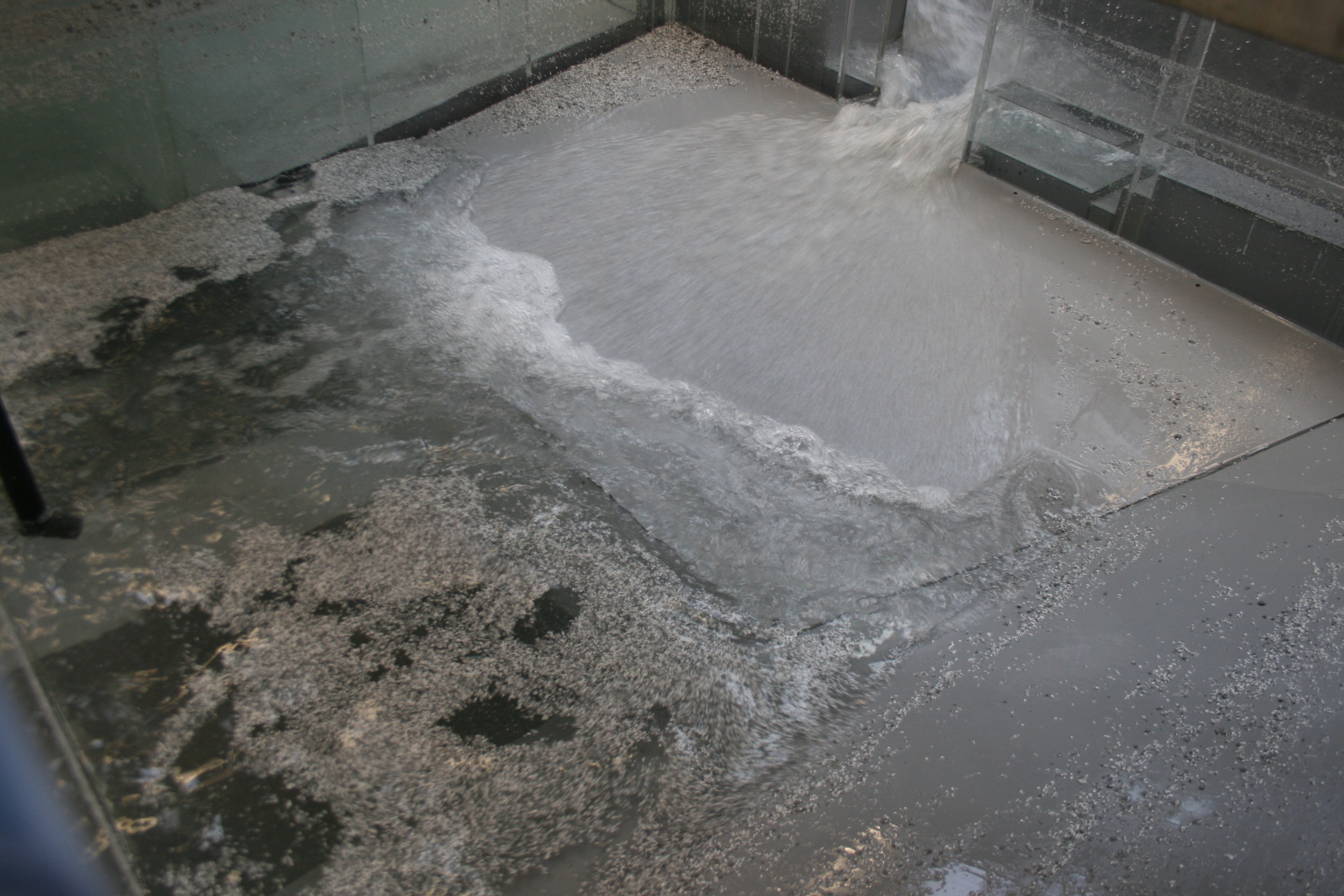
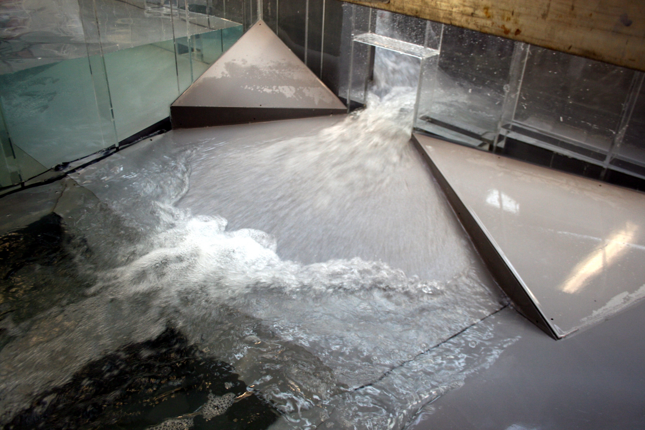
The physical hydraulic model study was required to investigate and confirm the pumping station hydraulics, the proposed operating philosophy and the self-cleansing characteristics of the initially proposed design. Where required, suitable modifications were developed to optimise each component of the overall arrangement to ensure that the pumping station remained self-cleansing in terms of grit and gross solids and that the pumps could operate in a hydraulically sound environment, regardless of inflow, pump designation and combination and sump water level.
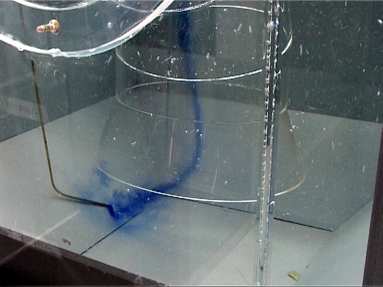
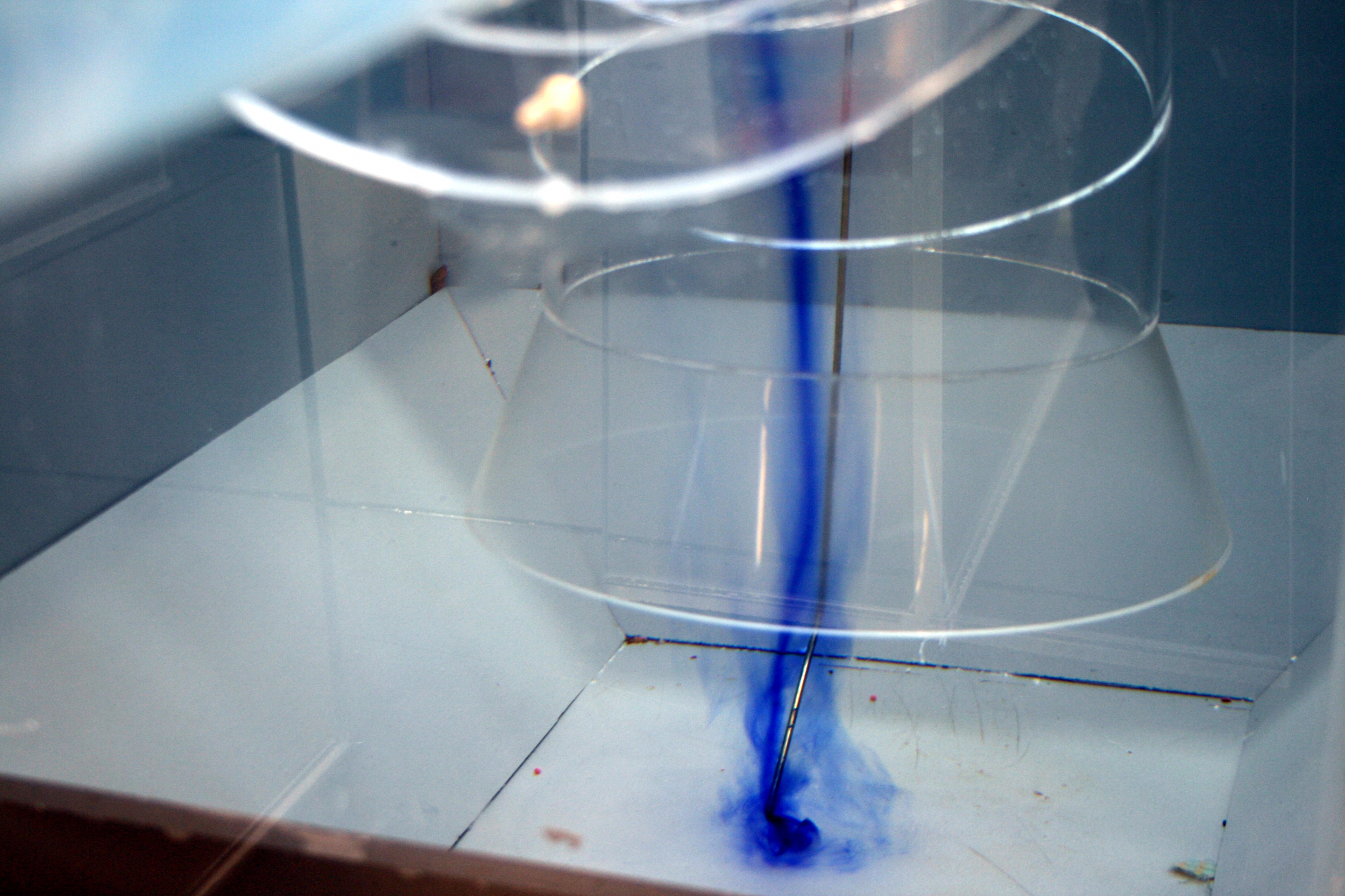
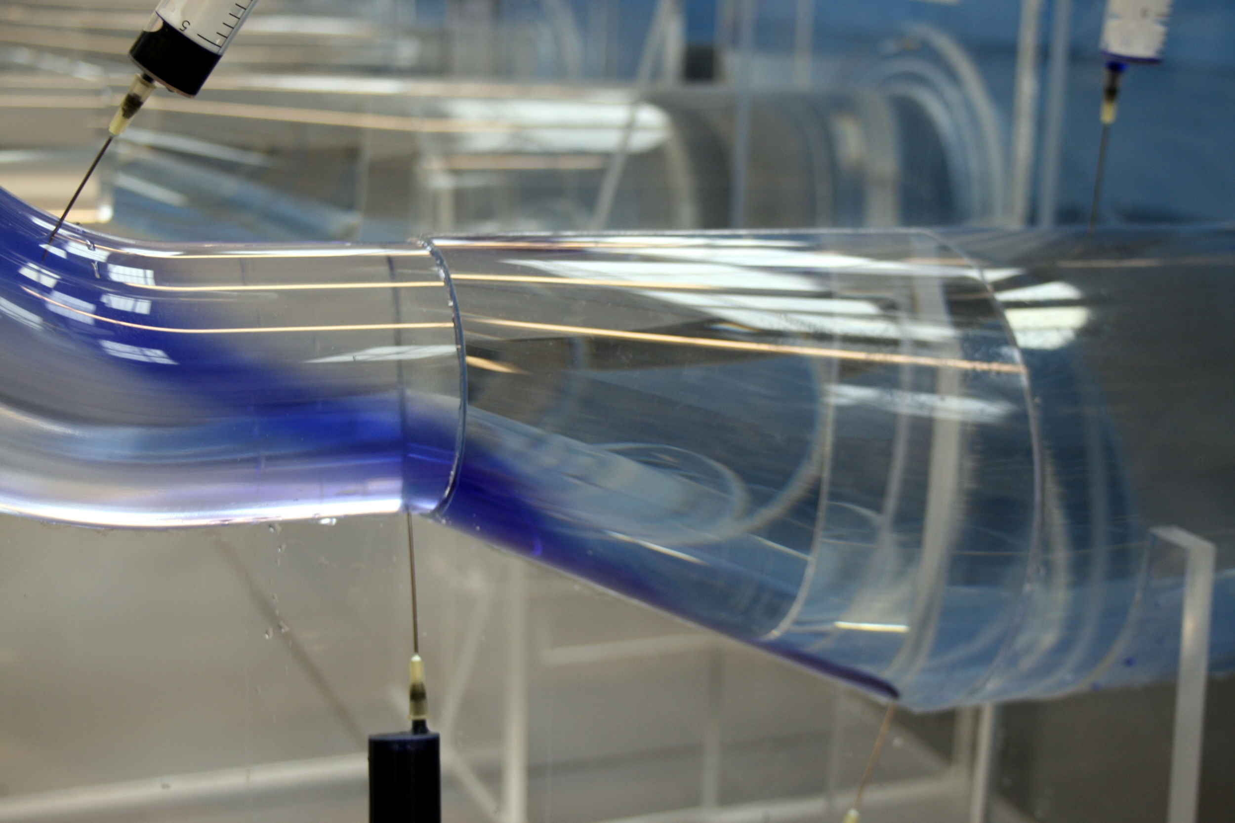
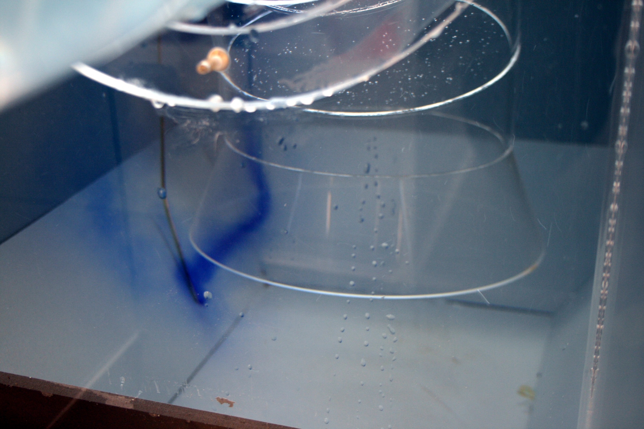
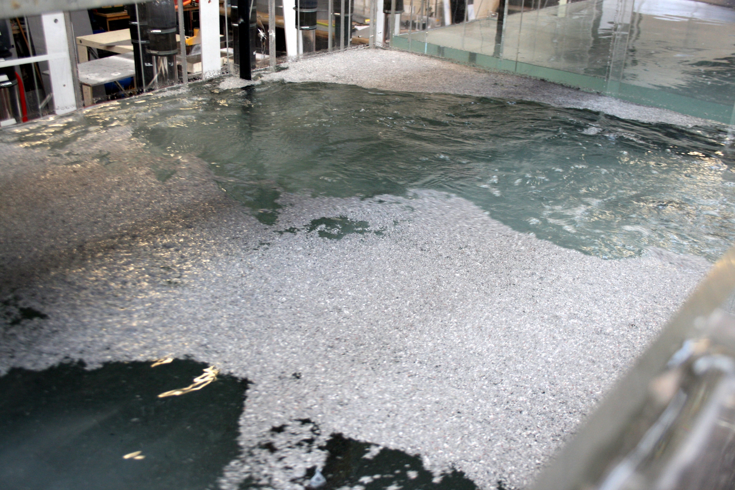
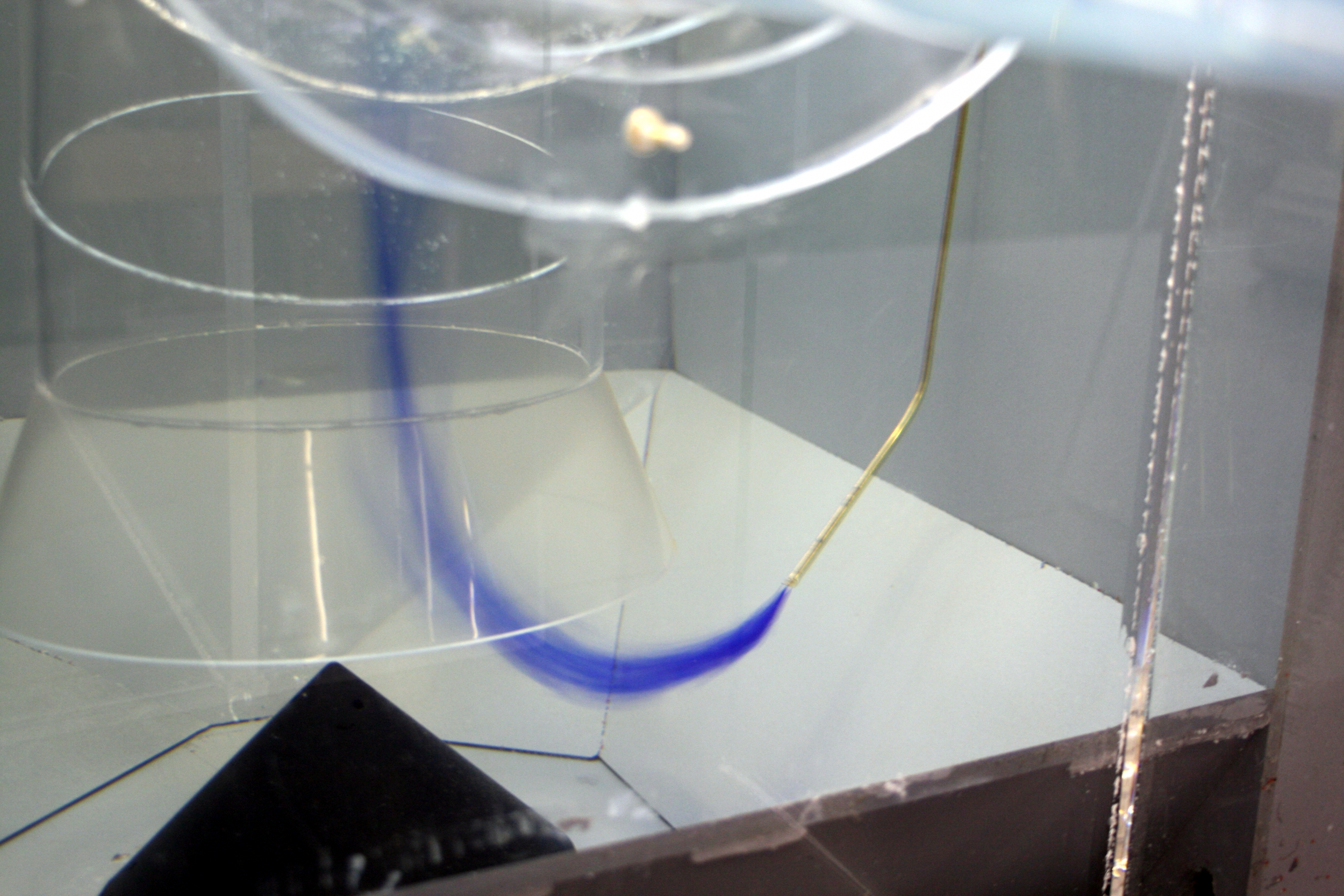
Testing of the initial proposed arrangement demonstrated evidence of submerged vorticity connecting with all operative pumps and an oblique suction draw, which initiated helical flow patterns within the suction pipework. While flow was able to re-stabilise within the long suction pipework, prior to reaching the pump impeller position, the swirling flow at the intake was considered sufficient to initiate ‘roping’ of fibrous solids, that may become trapped around the impeller, resulting in future maintenance issues. Several areas of solids deposition were also identified within the pumping station arrangement and there was a concern that buoyant debris would accumulate on the water surface and would not be cleared by the pumps.
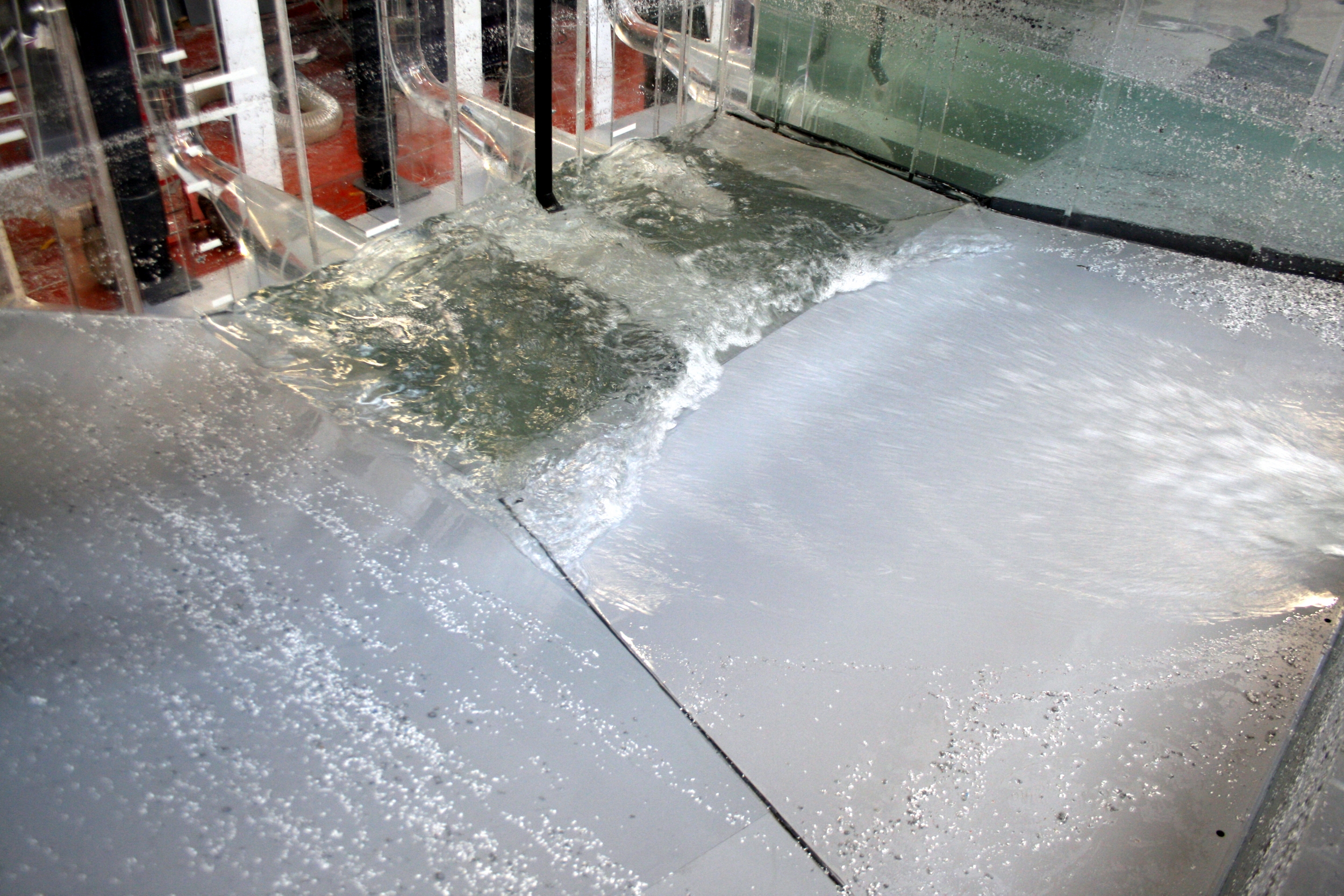
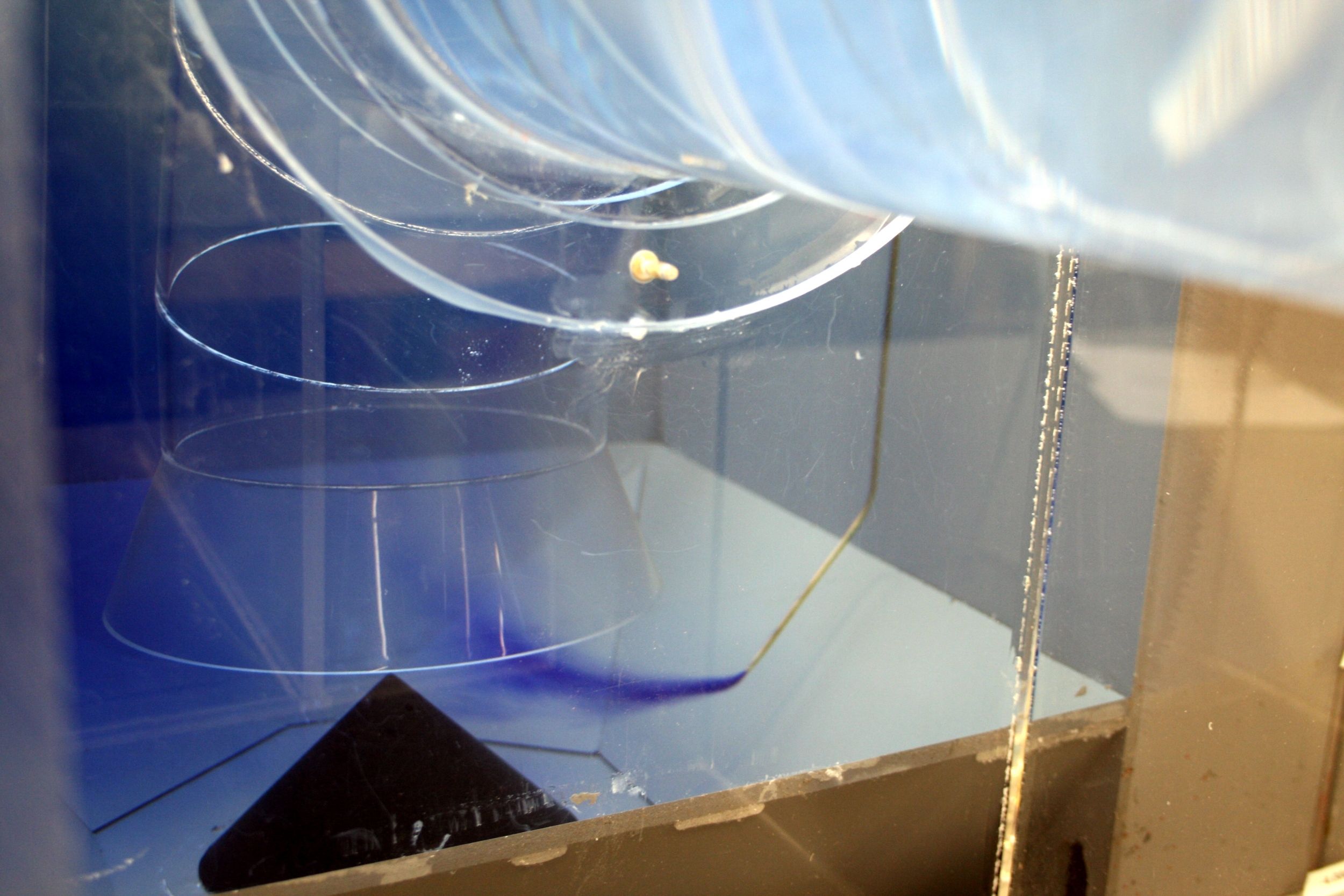
Following a detailed assessment of the initially proposed arrangement, the inlet reception area was modified, by means of twin flow deflectors, to allow improved energy dissipation and flow distribution, while reducing the volume of entrained air delivered into the sump. Further development of the reception chamber landings were incorporated to eliminate solids deposition, which included the adoption of strategically positioned infill benching. Flow conditioning modifications were incorporated into the pump extraction wells, which eliminated submerged vorticity, reduced swirling approach flow (negating our concerns for ‘roping’ of fibrous solids) and improved the draw of flow into the suction arrangement by stabilising the flow and inducing a more radial draw. In addition, further infill benching was proposed within the pump sump, that proved effective at eliminating zones of potential solids deposition.
Optimisation of the proposed operating levels and the introduction of a defined cleaning cycle were also incorporated into the operating philosophy, which ensured that the sump remained self-cleansing; hence, reducing long and short term maintenance requirements.
With the proposed modifications adopted onto the prototype, along with the defined control levels and operating philosophy, a hydraulically sound pumping environment was achieved and maintained across the full flow and level range, under both ‘normal’ and maintenance operating periods. In addition, the pumping station and associated inlet arrangement was now materially self-cleansing, in terms of positive, neutral and negative buoyancy particles. No further modifications were considered to be a requirement and the modifications proposed were relatively simple to install with no requirement to alter the pump positions or the structure of the station.
Moorfield Estate
Yeadon
Leeds LS19 7YA
e: info@hydrotecltd.co.uk
w: hydrotecltd.co.uk

