


- SOUTH JEDDAH - AL KHUMRA SCREEN CHAMBER AND PUMPING STATION
- BRA 3494 – Sabesp Sao Lourenco, High Pressure Pumping Station
- FRANKLEY DE-ALK TRANSFER PUMPING STATION
- Deephams FTFT Pumping Station and Inlet Culvert
- Riverside Sewage Treatment Works - Regional Sump 1
- La Villette Pumping Station
- Bewsey Bridge Pumping Station
- Suez Thermal Power Station - Intake Pumping Station
- Norway Road Pumping Station
- Grimonpont RAS Pumping Station
- Nab's Head Storm Inlet Channel and Storm Pumping Station
Pumping Stations
La Villette Pumping Station
Client: XYLEM FRANCE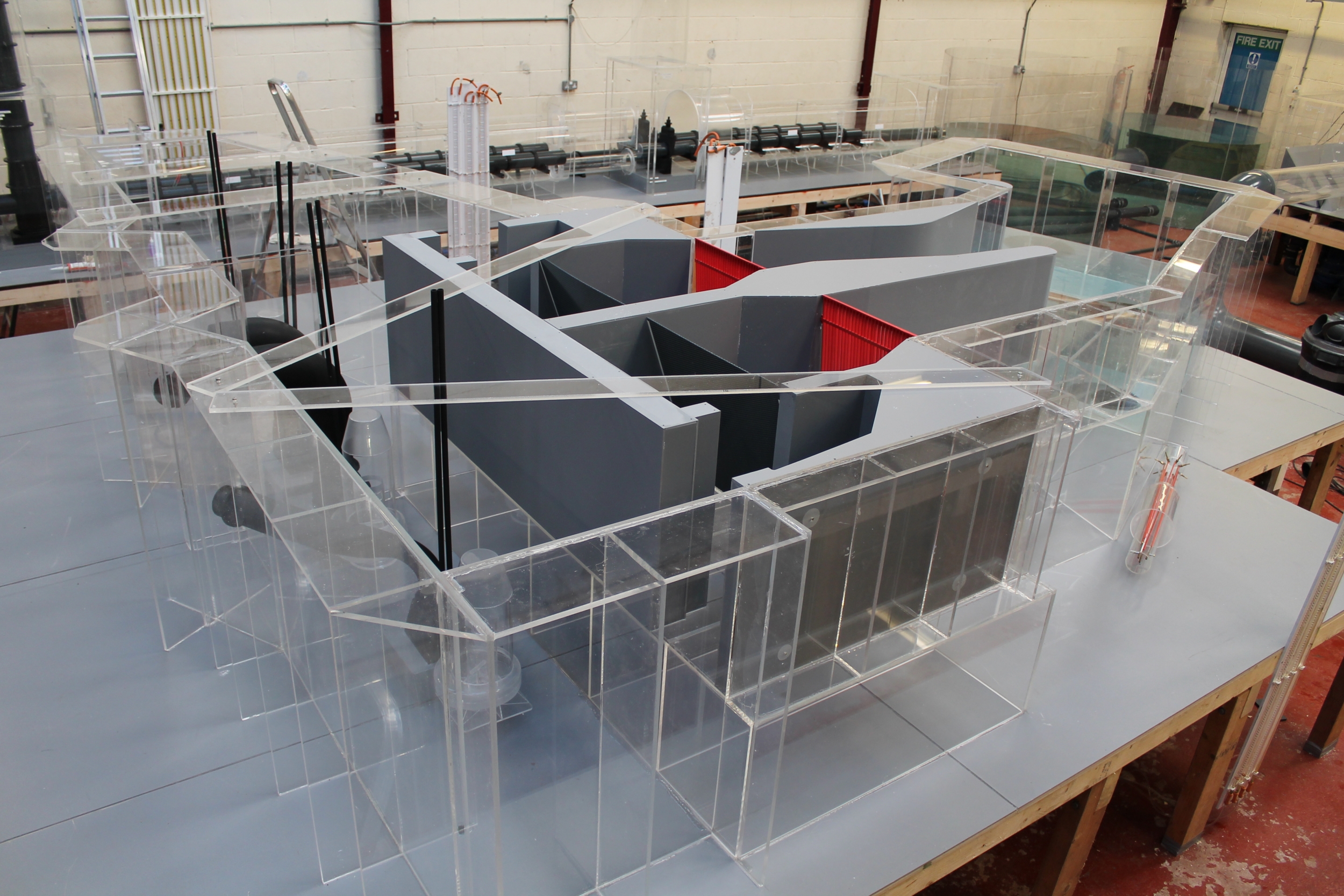
Scale: 1/5
The existing La Villette Pumping Station is be refurbished, with the existing submersible pump sets to be replaced with the following:-
- 2 x Flygt CP 3531-935 Submersible units. Flygt Drawing 576900
- 2 x Flygt CP 3351-905 Submersible units Flygt Drawing 5744400
The CP 3531-935 units will deliver a peak flow of 1111.2 l/s and the CP 3351-905 will deliver a peak flow 639 l/s. The pumps will be located in a similar position to the existing pump units, the effluent to the pumping station will be clean water and hence, there is not requirement to review solids transport within this model study.
Several pumping station options were considered by the Client and it was confirmed that Option1, “solution de base” or submersible pump option has been confirmed.
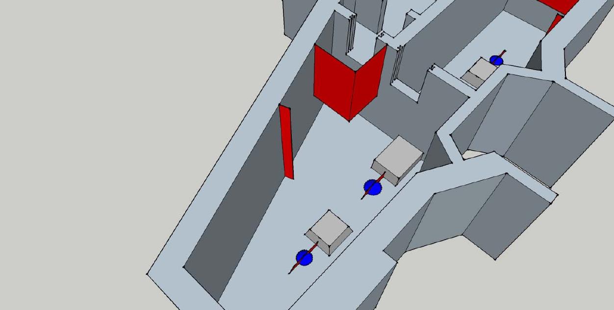
The sump includes two inlets, one feeding each side of station, the two sides of the station can be isolated by means of penstocks located between pumps P2 and P3 at the upstream end.
The two inlets each comprise isolation penstocks, a 20mm coarse bar screen with rake and 3.0mm drum screens followed by further isolation penstocks. In addition the Client had stipulated that 0.300m loss would be anticipated between the sump and upstream water level. A 100mm diameter balance pipe is also provided between the two main wells, which may also be gravity feed line for when the pumps are not running.
The initial testing programme identified significant areas of non-compliance within the La Villette pumping station with Type 3 submerged vorticity identified as the most detrimental to acceptable pump operating conditions. Flow entered the sumps in a relatively high velocity jet due to constriction of flow through the entry ports. The high velocity flow had enough energy to initiate mass bulk rotation with each sump creating significant cross flow local to the pump suctions. The direction of the mass bulk rotation was dependant on sump designation i.e. clockwise or anti-clockwise. Sump one experienced an anti-clockwise mechanism with sump two exhibiting clockwise rotation, their respective locations within the station was the primary factor in determining the bulk rotational direction.
The noted mass bulk rotational flow within each sump created significant cross flow local to the operative pump suctions. As such, each pump experienced excessively high pre-swirl values and associated submerged vorticity. All pump units, regardless of combination or water level experienced stable and coherent Type 3 to Type 2 submerged vorticity, oblique flow entry and significant turbulence local to the intakes.
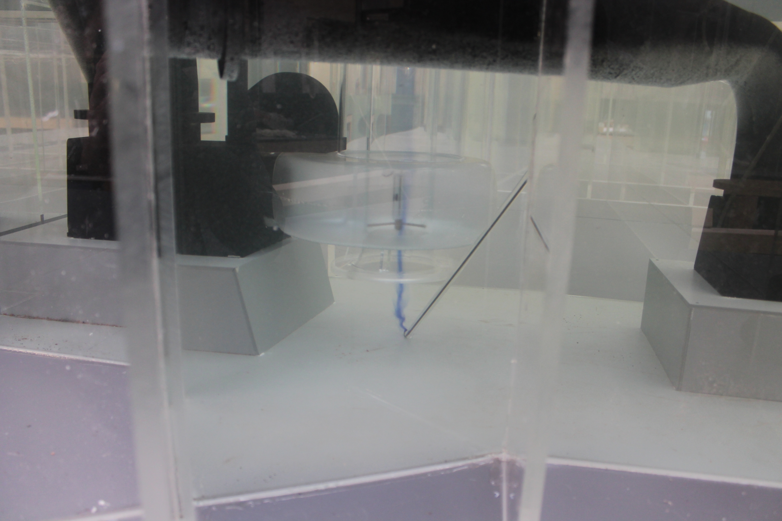
To further qualify the observations local to the pump intakes, four pitot scans were undertaken. The scans indicated the velocity distribution at the pump impeller and ascertained any disturbances or turbulence over a representative cross section of the pump impeller blade.
The pitot scans on all four pumps indicated significantly poor intake velocity distribution with further evidence of the observed sub-surface vorticity at the centre of the pump units, such values as the recorded (minus 84.32% variation) indicated the presence of coherent Type 3 sub-surface vorticity.
Following review of the existing arrangement, numerous options were required to correct the adverse flows within the vicinity of the four pump intakes. The suggested modifications are sympathetic to site constraints i.e. access to the wet well could be difficult to access. Therefore, some modifications could be split into manageable sections and retro-fitted within the wet wells. No structural changes or re-location of the pumps is proposed. We would consider the following proposals to optimise the existing arrangement for both sump arrangements:-
Sump 1
- Suspended baffle:-
The suspended baffle intercepts the high velocity flow on entry to the sump and suppresses the bulk re-circulatory flow path observed in the initial assessment. Included in the suspended baffle is an intermediate opposing baffle which promotes lateral approach flow to the pumps.
- Flow tripper:-
Installed within the sump is a vertically mounted flow tripper located on the external wall. The flow tripper further promotes flow direction to pump M1 and supresses the re-circulatory flow path within the sump.
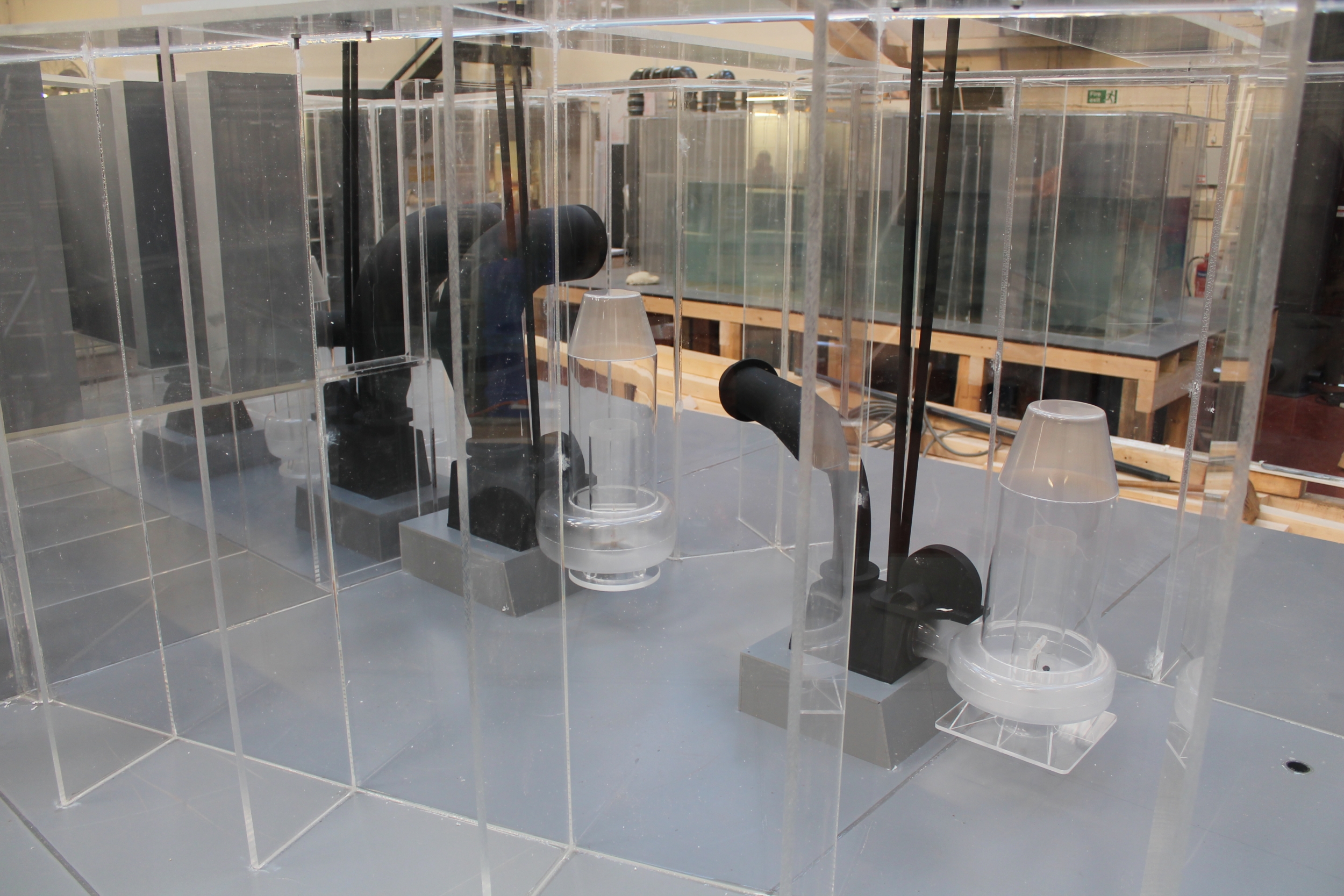
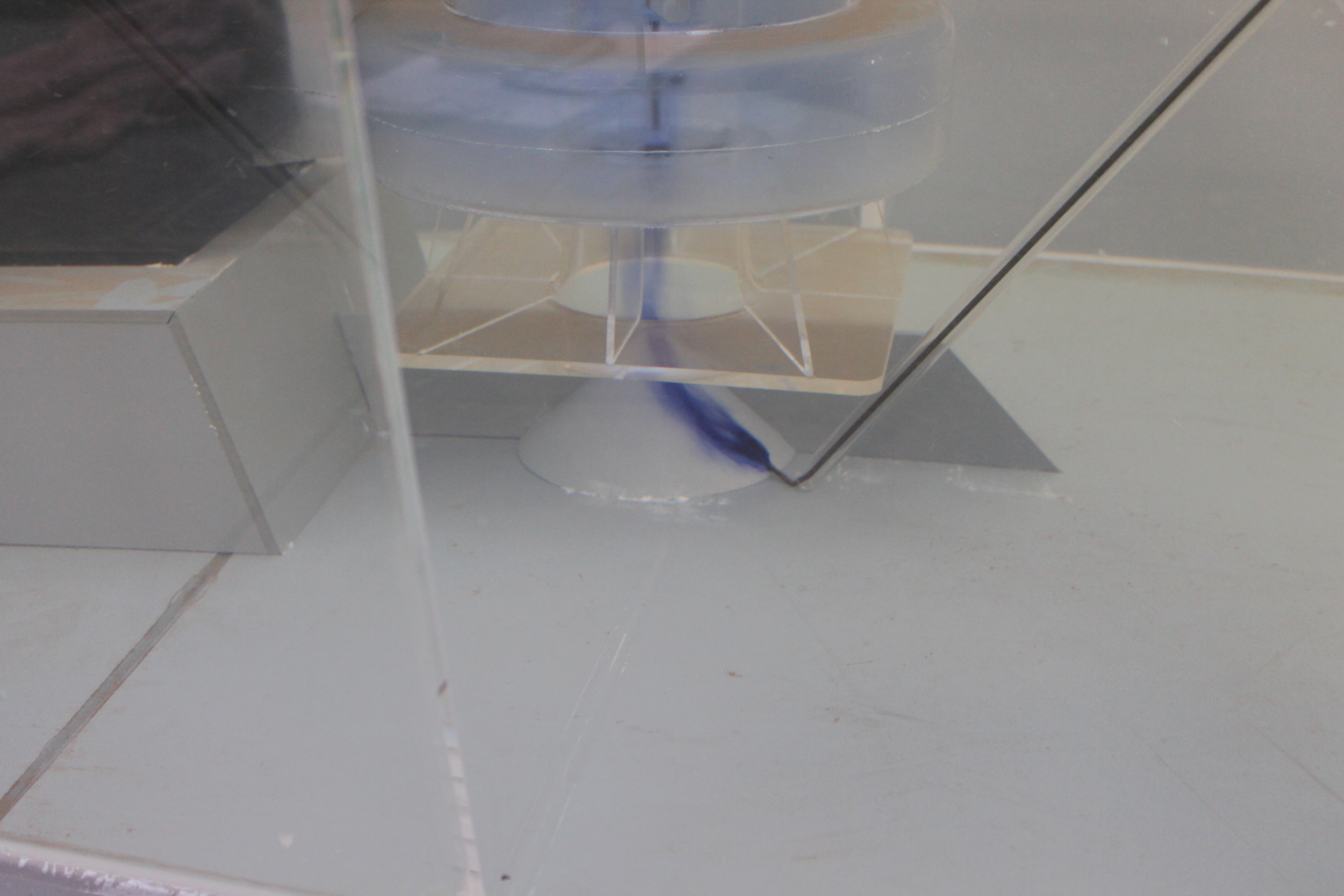
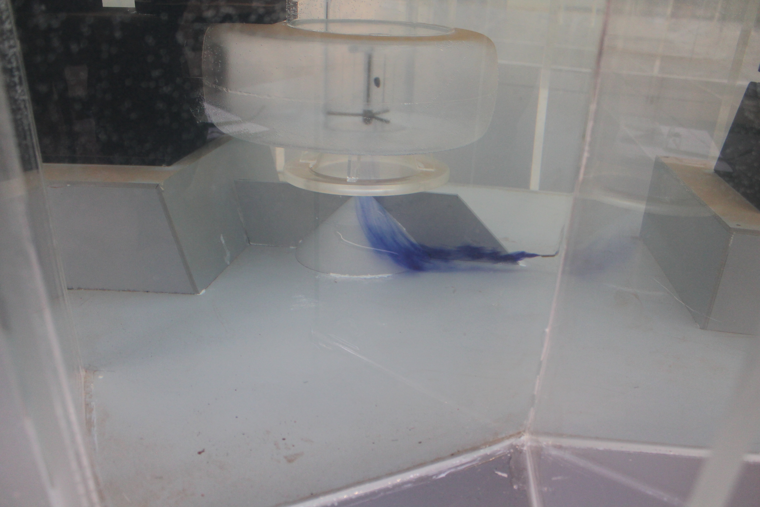
- Suction cone and vane:-
The suction cone and single element vane are required to promote a uniform velocity profile on entering the pump suction. The single element vane will further address the oblique flow characteristics observed within the initial assessment with promotion of uniform intake conditions. The cone installed centrally, will supress the coherent sub-surface vorticity. The cone will deny the vorticity a formation point, thus reducing the phenomena from forming.
Sump 2
- Baffle box:-
The installed baffle box supresses the flows tendency to track the external wall of the sump and initiate the bulk re-circulation observed in the initial assessment. With the baffle box installed flow will be re-directed to the invert of the sump.
- Flow trippers
The installed flow tripper will re-direct the flow within the sump to allow forward approach flow to each of the pump units and suppress the bulk rotation observed previously.
- Suction cone and vane:-
The suction cone and single element vane are required to promote a uniform velocity profile on entering the pump suction. The single element vane will further address the oblique flow characteristics observed within the initial assessment with promotion of uniform intake conditions. The cone installed centrally, will supress the coherent sub-surface vorticity. The cone will deny the vorticity a formation point, thus reducing the phenomena from forming.
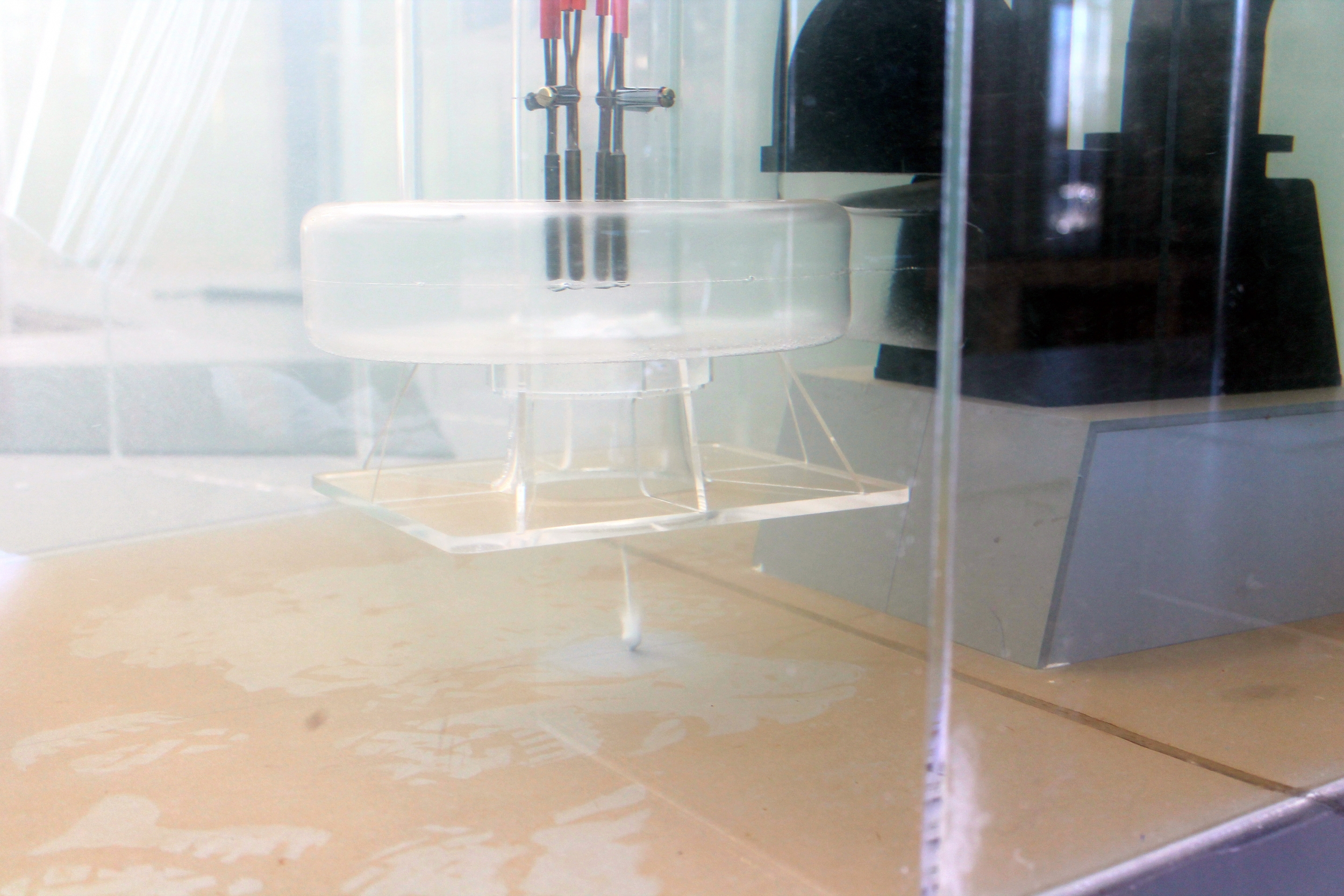
Final testing
With the adopted modifications installed, a satisfactory pump operating environment was achieved. Acceptable pump intake conditions were maintained throughout the operating range and pump combinations. The pump suctions operated in an environment free from submerged and free surface vorticity with pre-swirl rotation maintained well within acceptable limits. At no stage was air entrained to the pump suctions on the proviso that the operating levels defined from testing are adhered to.
Moorfield Estate
Yeadon
Leeds LS19 7YA
e: info@hydrotecltd.co.uk
w: hydrotecltd.co.uk

