


- SOUTH JEDDAH - AL KHUMRA SCREEN CHAMBER AND PUMPING STATION
- BRA 3494 – Sabesp Sao Lourenco, High Pressure Pumping Station
- FRANKLEY DE-ALK TRANSFER PUMPING STATION
- Deephams FTFT Pumping Station and Inlet Culvert
- Riverside Sewage Treatment Works - Regional Sump 1
- La Villette Pumping Station
- Bewsey Bridge Pumping Station
- Suez Thermal Power Station - Intake Pumping Station
- Norway Road Pumping Station
- Grimonpont RAS Pumping Station
- Nab's Head Storm Inlet Channel and Storm Pumping Station
Pumping Stations
Suez Thermal Power Station - Intake Pumping Station
Client: Hitachi Pumps
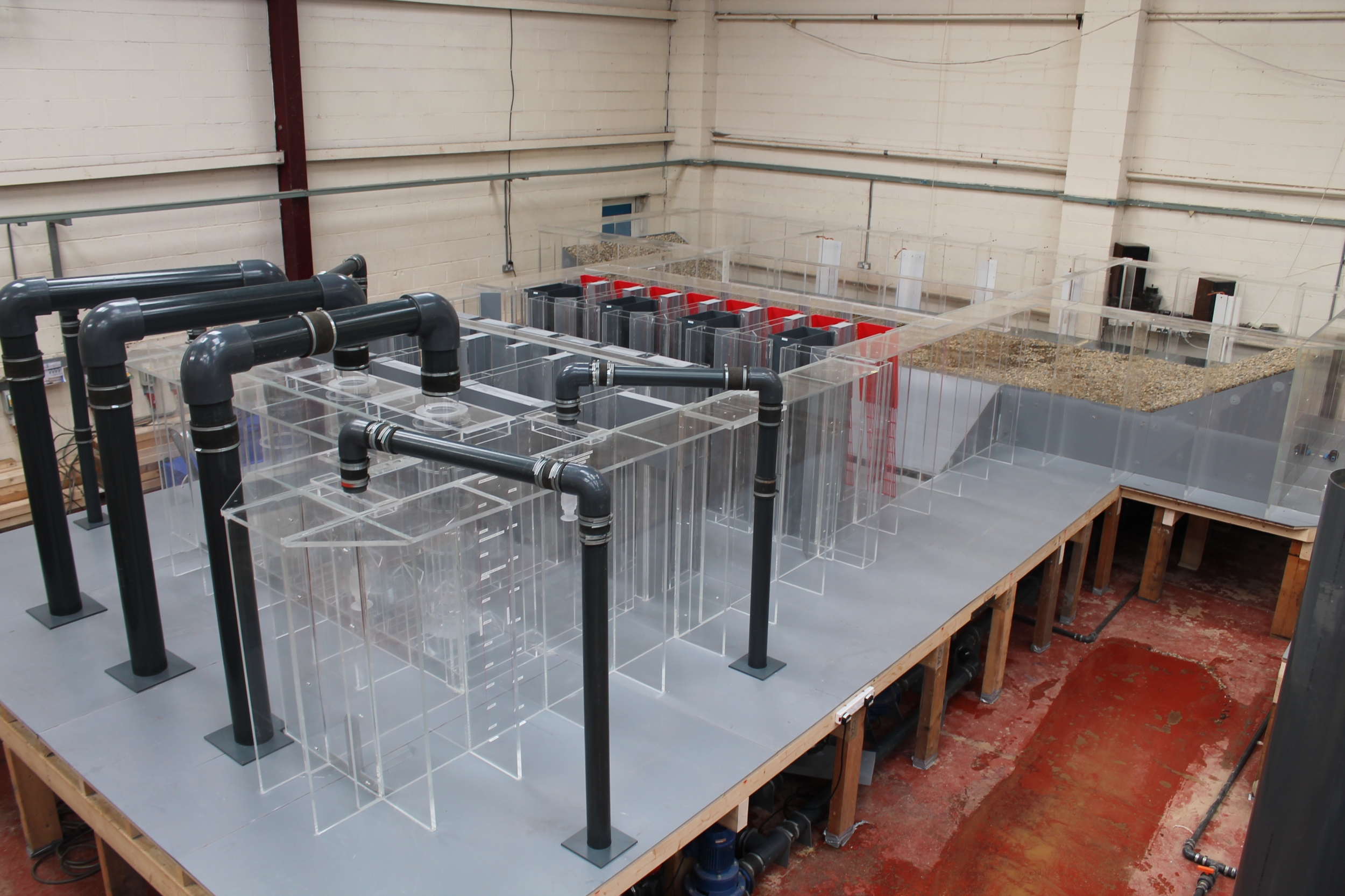
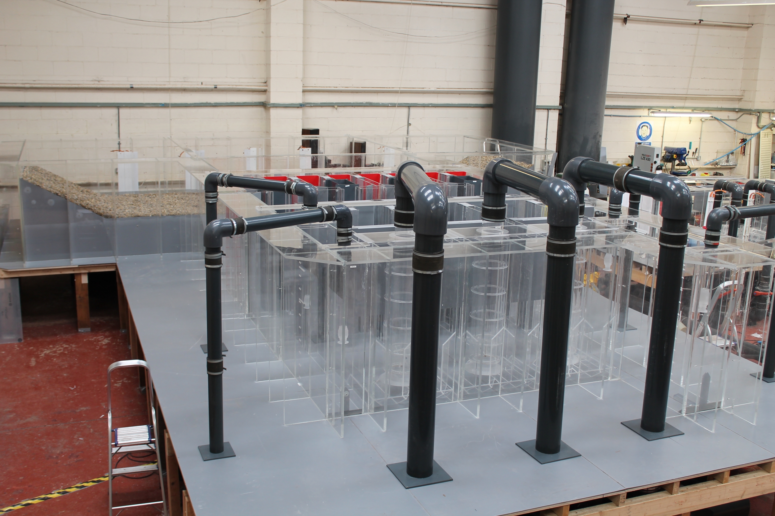

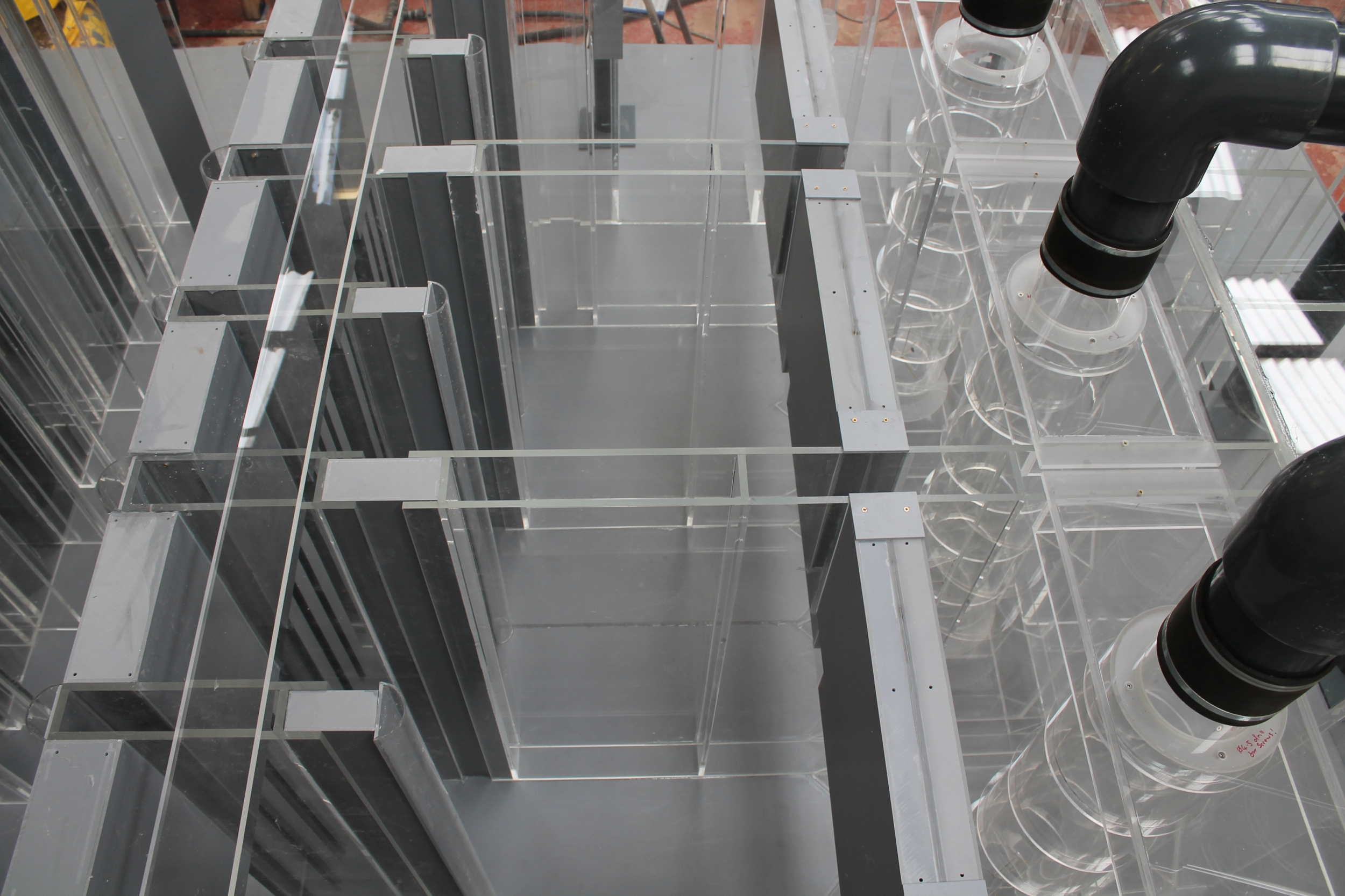
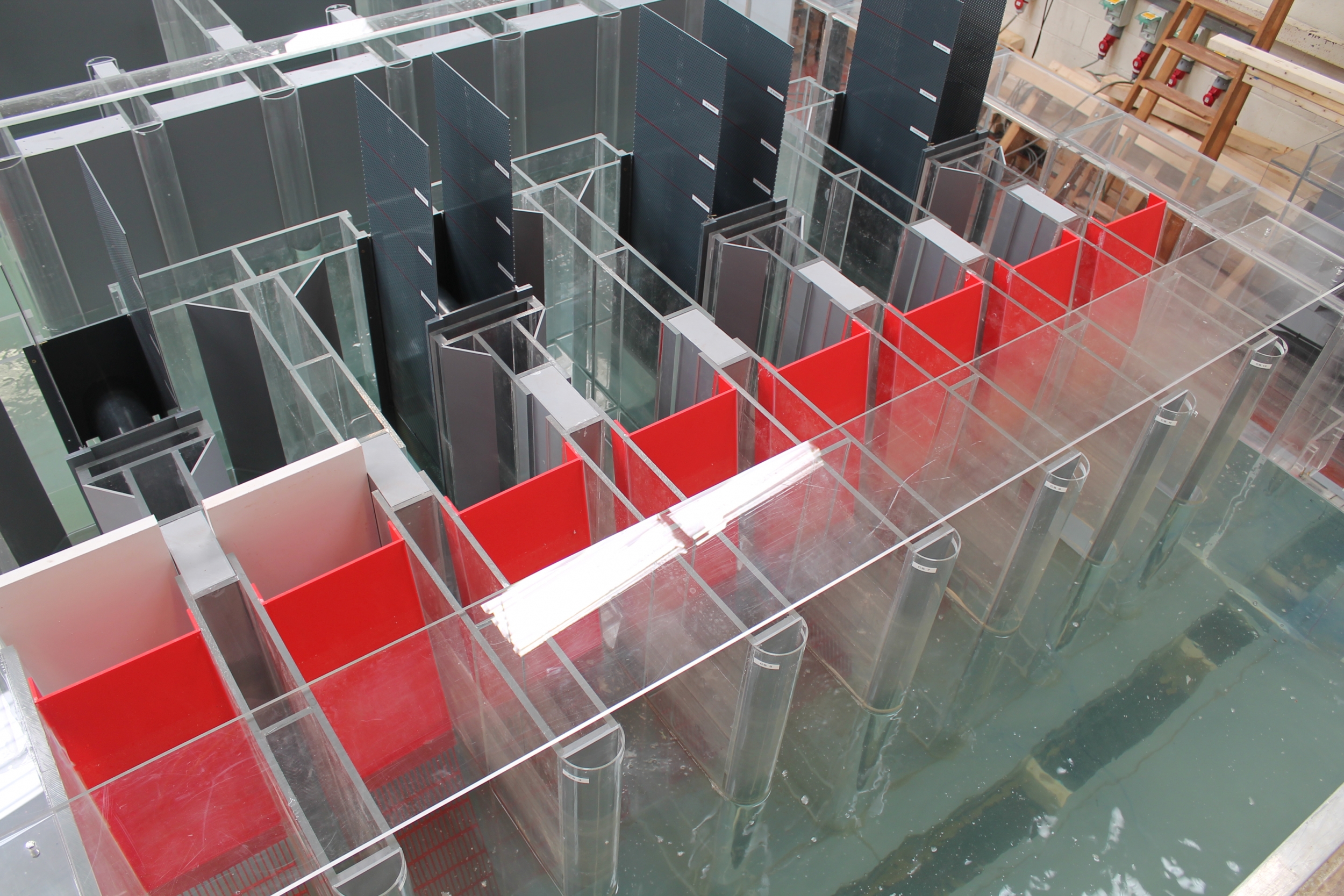
Scale: Main model 1/10th, with one (of two) SW/DW pump cells modelled at 1:7th scale.
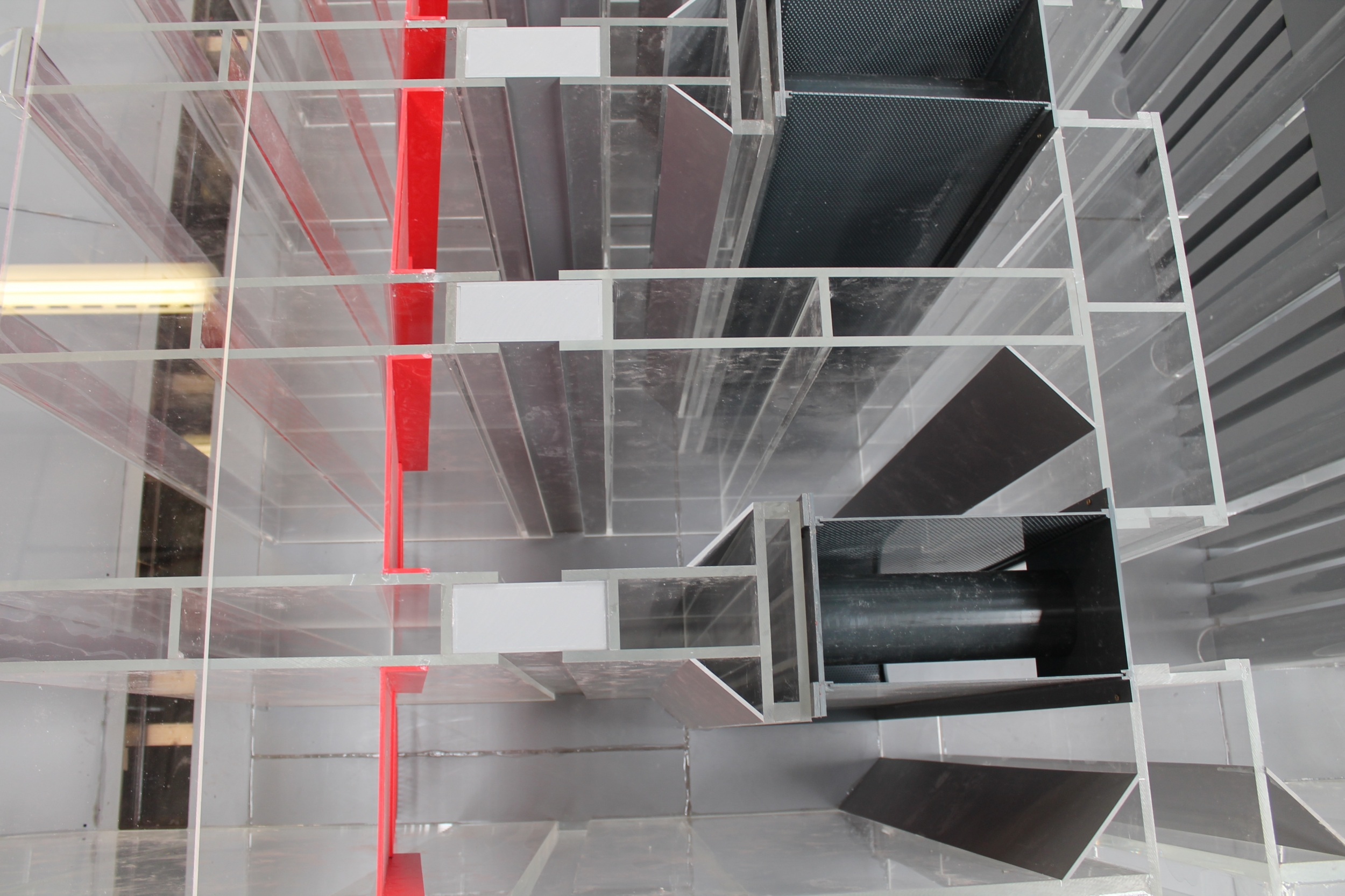
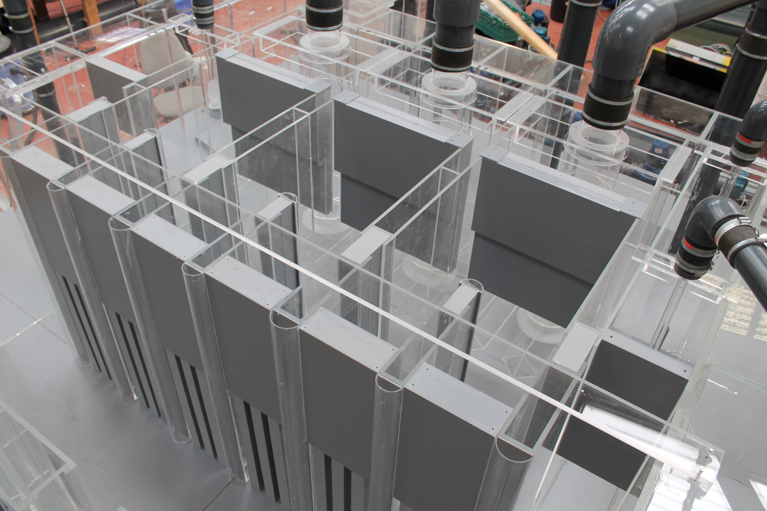
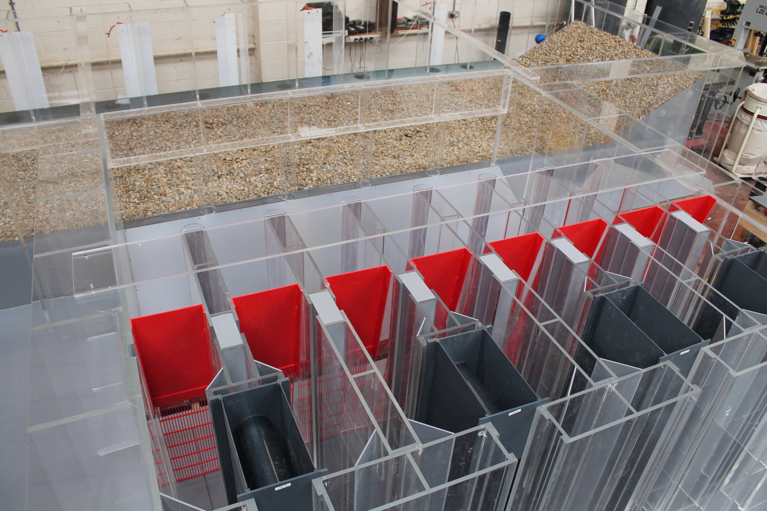
The Suez Thermal Power Station is located approximately three kilometres South of Suez City (Ettaqa District), Egypt, and consists of one 650 MW gas/oil fired unit. The plants cooling water system is a once through circulating water (CW) system, withdrawing water from the Suez Bay, via an off-shore breakwater channel and discharging the heated water back to the bay through a shoreline discharge structure. The off-shore breakwater intake channel has been designed to provide settling of any suspended solids and to provide a uniform approach flow to the shoreline pump intake structure. The onshore pump intake structure is a vertical wet pit type and houses eight bar screens, four dual flow travelling band screens, three vertical wet well mounted Circulating Water Pumps (CW Pumps), two vertical wet well mounted Service Water Pumps (SW Pumps), two vertical wet well mounted Desalination Feed Water Pumps and three vertical screen wash pumps.
The CW Pumps will be located centrally within the pumping station arrangement and have an intake diameter of 3.0 m. They are a fixed speed unit that will operate on a duty/assist/standby basis and be capable of delivering an individual flow of 12.78 m3/s. The SW Pumps will be located both sides of the three central CW Pumps and have an intake diameter of 0.64 m. These pumps are fixed speed units and will operate on a duty/standby basis, being capable of delivering an individual pumped flow of 0.45 m3/s.
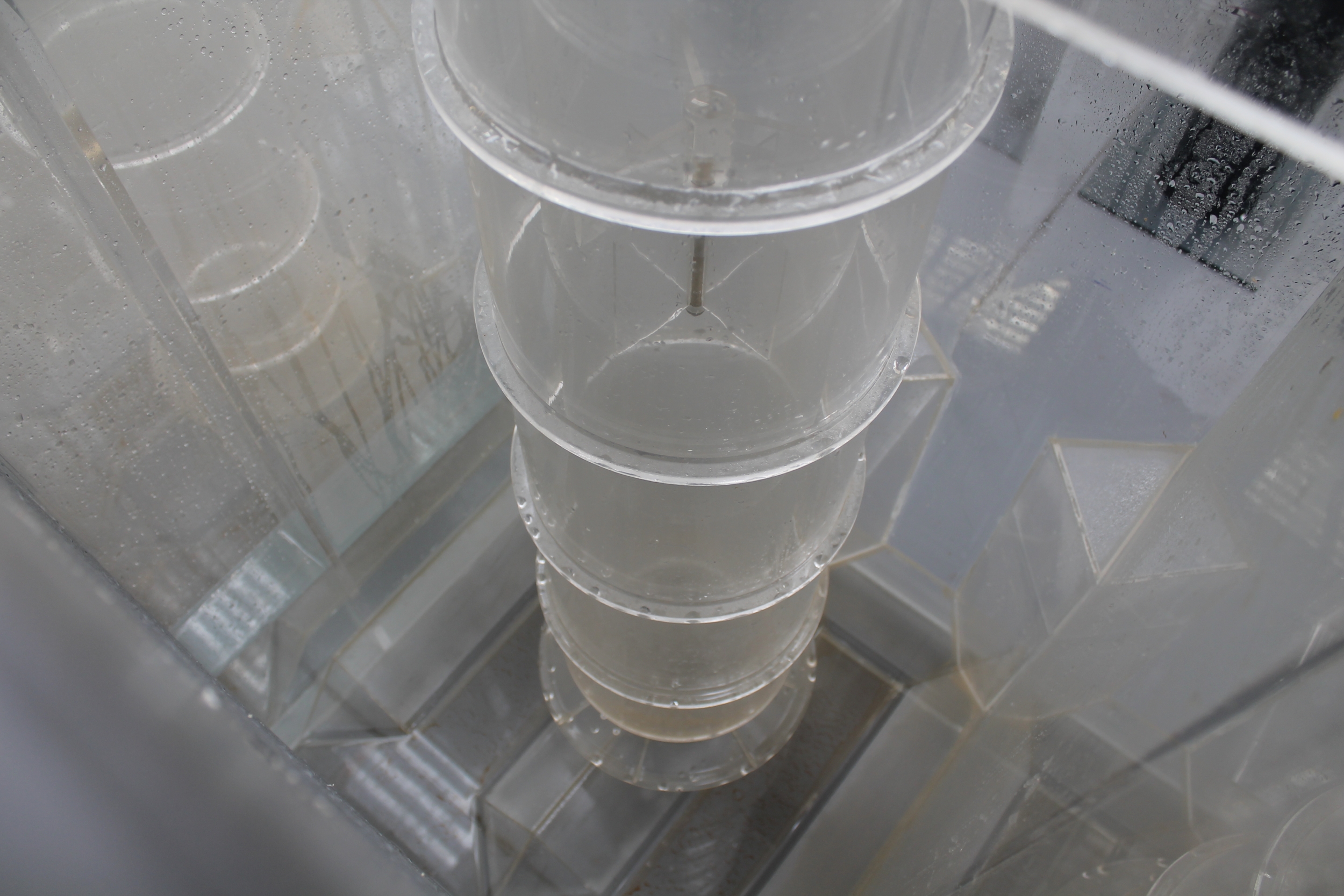
Due to the significant variation in physical size and capacity of the operative CW, SW and DW pumps, determining a model scale that ensured dynamic similarity between the model and prototype was maintained simultaneously for all operative pumps, within a realistically sized test rig, was not possible. To overcome this, it was agreed with the client that a distorted scale model be constructed, where one of the two Service Water Pump chambers could be adapted to represent either a 1:10th scale cell (coincident with the main model and for studying general flow patterns and the influence of the SW cell on the operation of the adjacent operational (CW) cells) or a 1:7th scale cell (allowing a detailed assessment of pre-swirl rotation and cross sectional velocity profiles, whilst simultaneously satisfying the scaling requirements).
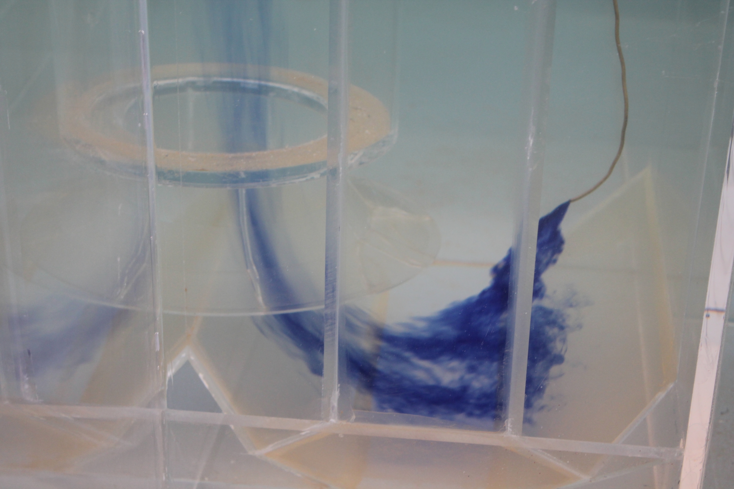
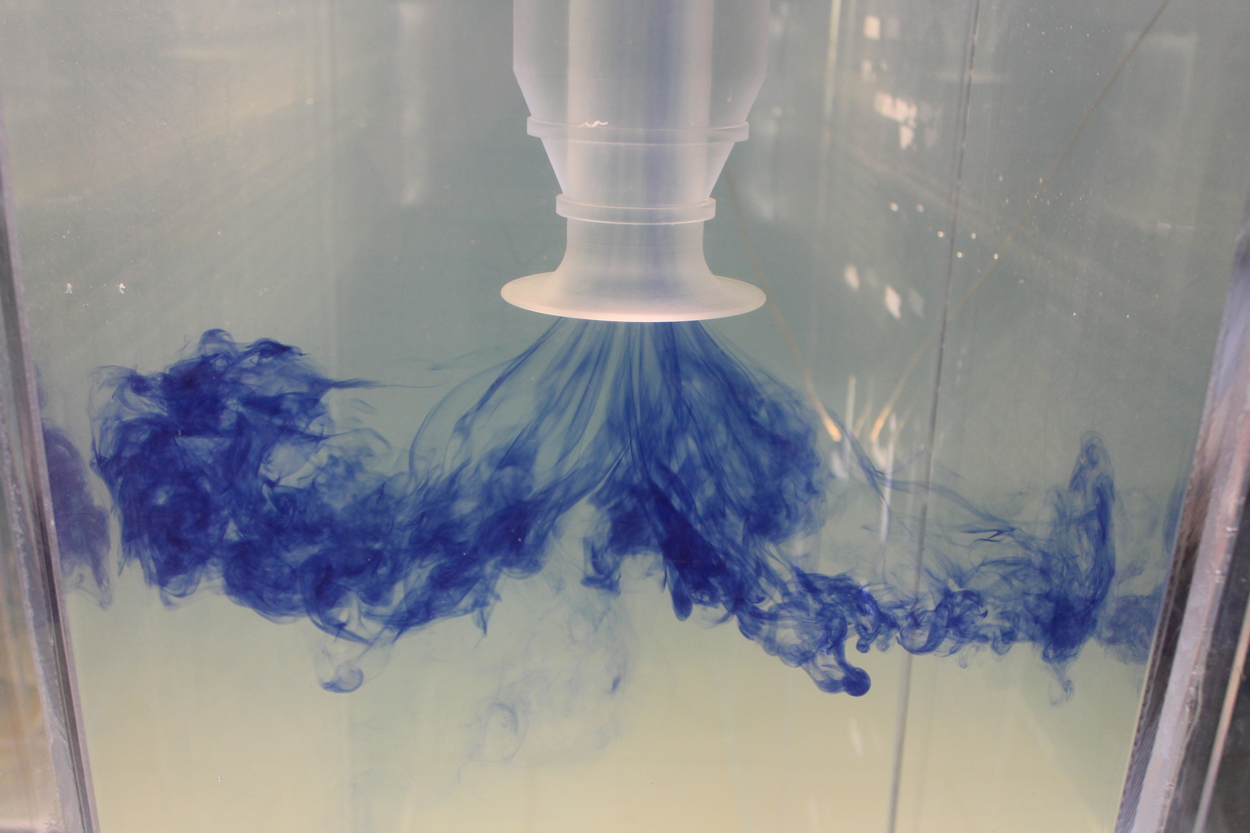
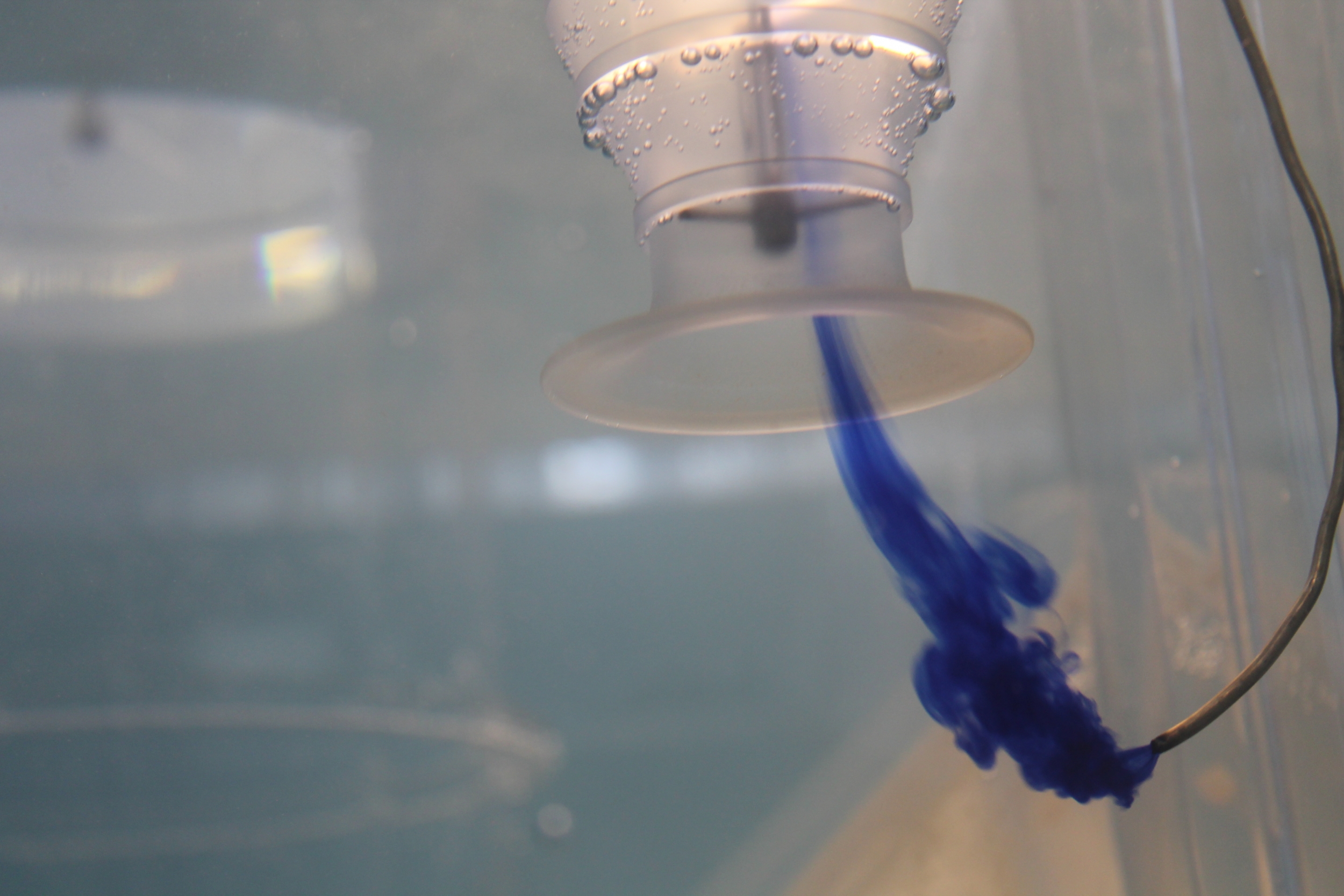
Testing demonstrated that the conceptual design of the proposed Suez Intake Pumping Station was generally sound and only minor development was required local to the Desalination Water Feed Pump intakes, to eliminate submerged vorticity and hence, to provide a hydraulically acceptable operating environment.
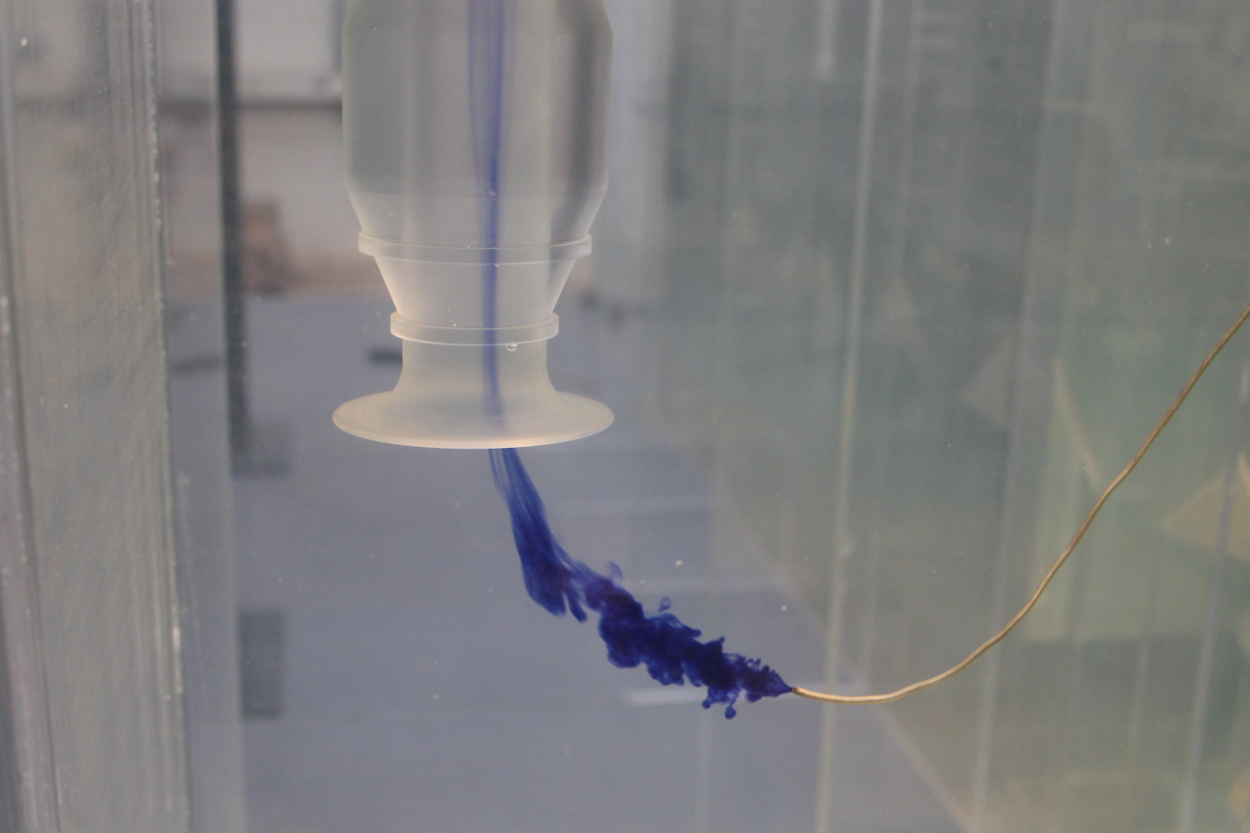
Elimination of the submerged vortices was achieved by the development of vortex suppression plates, fixed to the two side walls of the sump, local to the intake position of the two Desalination Feed Water Pumps, in addition to a reduction in the height of the suspended baffle wall, located at the upstream end of the SW/DW Pump cells. No further development was required and it was considered that with the proposed modifications adopted, a hydraulically sound operating environment would be achieved for all pumps, irrespective of combination, designation and operating level.
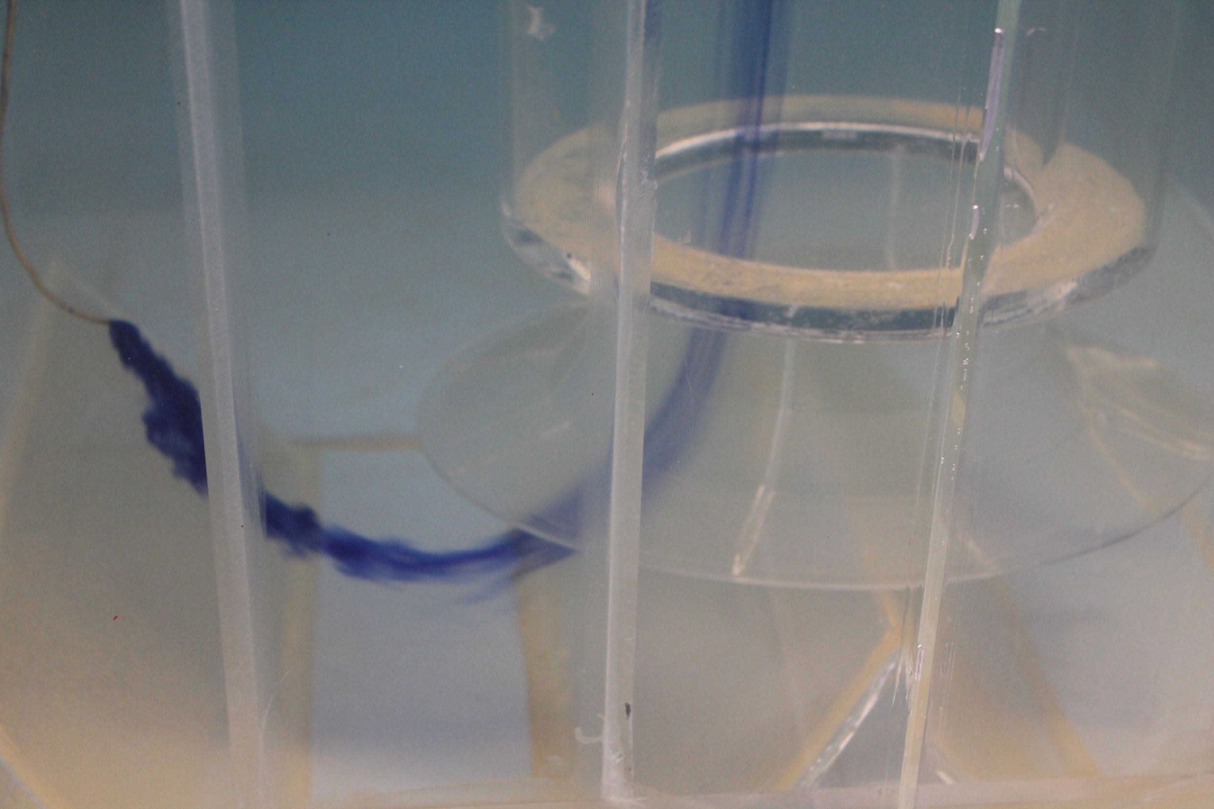
Following development and optimisation of pump intake conditions, testing demonstrated that draw of flow at the pumps was characterised by a stable and uniform approach profile that was free from turbulence, jetting, stall areas, swirl and separation, with a smooth and uniform radial suction draw. All pumps were free from excessive pre-swirl rotation, with peak values maintained below 1.0 degree in all cases (based on 10, 30, 60 and 600 second models). There was an absence of both free surface and submerged vortices local to the pumps and no evidence of entrained air within the vicinity of the pump suctions (hence, any potential for air bubble ingestion was eliminated).
Cross sectional velocity profiles were measured at the pump impeller position, using pitot static tube arrays, which demonstrated little evidence of velocity deviation from the calculated mean and full compliance with the recommended tolerances. Each of the pumps tested maintained operation in accordance with the ANSI/HI 9.8-2012 standard.
An assessment of screen flow distribution was undertaken for various combinations and number of operative screen channels and the results demonstrated that the peak values of variation were within acceptable limits. In addition, the cross sectional profile onto each of the individual operative screen elements was assessed, to determine any evidence of biasing or reverse flow patterns local to the screens (which could adversely influence the attachment of screenings and/or provide biasing and subsequent premature blinding to defined areas of the screen elements).
In conclusion, the design of the pumping station arrangement was considered to be acceptable and only very minor alteration was required to eliminate the submerged vortex activity local to the Desalination Pumps. No further development was required and it was considered that with the proposed modification installed, a hydraulically sound operating environment would be achieved for all pumps, irrespective of combination, designation and operating level.
Moorfield Estate
Yeadon
Leeds LS19 7YA
e: info@hydrotecltd.co.uk
w: hydrotecltd.co.uk

